McIntosh MIP200 handleiding
Handleiding
Je bekijkt pagina 9 van 16
9
MIP200
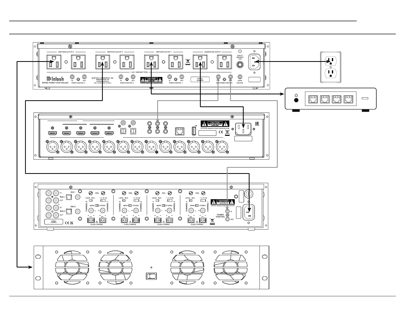
MIP200 Connection Diagram
HDMI
IN
1 2
3
4
RS232
TRIG 1 IR IN
TRIG 2
2
OPT
COAX
1
1
2
OUT/eARC
DATA OUTSETUP MIC
SERIAL
NUMBER
BALANCED OUTPUTS
RF LF C LS RB LB RH1RS LH1 RH2 LH2 SW1 SW2
NET
DIGITAL INPUTS
SERVICE
USB
5V/1A
NET NET NET NET
In this connection example, a home theater
processor, power amplier, network router
and equipment rack fan are shown connected
to the MIP200. The processor is connected to
the UNSWITCHED OUTLET so it always has
power and would be in standby mode.
The router and amplier are connected to
SWITCHED OUTLETS that have been cong-
ured to be ON. By being congured to ON they
act as additional unswitched outlets so they
always have power as well. A power control
signal from TRIG 1 of the processor will then
turn on the MIP200 front panel and then turn
on the amplier.
The equipment rack fan is connected to
SWITCHED OUTLET 3 which is congured to
only come on with MAIN POWER CONTROL.
By being congured for MAIN POWER
CONTROL the fan will only come on when the
system is turned on by the processor.
Bekijk gratis de handleiding van McIntosh MIP200, stel vragen en lees de antwoorden op veelvoorkomende problemen, of gebruik onze assistent om sneller informatie in de handleiding te vinden of uitleg te krijgen over specifieke functies.
Productinformatie
| Merk | McIntosh |
| Model | MIP200 |
| Categorie | Niet gecategoriseerd |
| Taal | Nederlands |
| Grootte | 2367 MB |