InfiRay BOLT TL35 V2 handleiding
Handleiding
Je bekijkt pagina 18 van 26
32 33
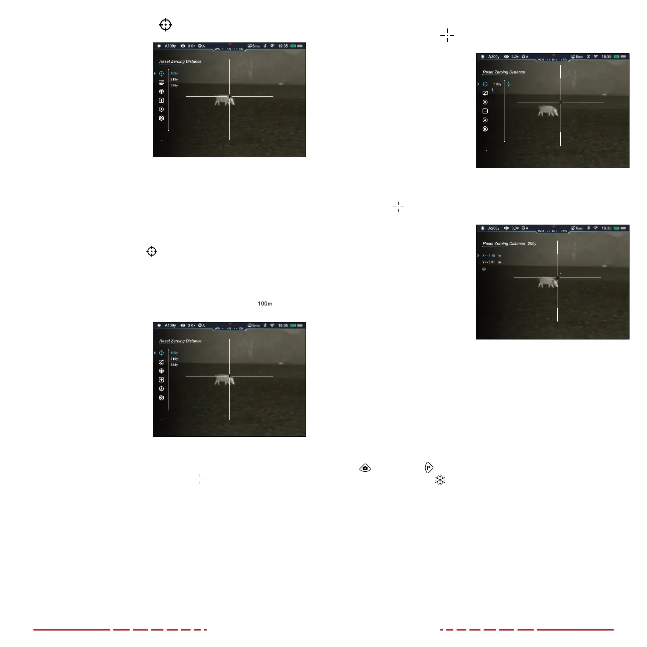
Reset Zeroing Distance
Select or customize zero
distance
In the reset zeroing distance
menu, you can select a preset
zero distance, customize a
preset zero distance, and
adjust the reticle position for
the selected zero distance.
The TL35V2 supports custom
zero distances of 1 to 999
yards or 1 to 999 meters.
NOTE: Before selecting or customizing a zero distance, you must
select a rifle zeroing profile, A, B, or C. See Main Menu > Rifle
Selection on the previous page.
1. Long press the Control Turret to enter the main menu.
2. Rotate the Control Turret to move through the menu to select
the reset zeroing distance
menu item.
3. Short press the Control Turret to enter the zeroing submenu.
There are three zero distances available in the submenu.
ZEROING MENU > ZERO DISTANCE SUBMENU
Select or customize a
preset zero distance
1. In the zero distance
submenu, rotate the
Control Turret to select a
zero distance.
2. Short press the Control
Turret to enter the
submenu for the selected
zero distance.
3. In the submenu for the
selected zero distance, you may:
a. Enter the reticle zeroing interface
to adjust the
X/Yposition of the reticle at the selected zero distance. See
Reticle Zeroing on the next page.
b. Customize the selected preset zero distance, as needed.
See Zeroing Menu > Customize Zero Distance on
page34.
ZEROING MENU > ZERO DISTANCE SUBMENU >
RETICLE ZEROING
Adjust the reticle position
of the selected zero
distance.
In the reticle zeroing interface,
the X/Y position of the reticle
may be adjusted to match the
point of impact. Refer back to
Zeroing the BOLT TL35V2 on
page21, if necessary.
1. In the submenu for the
selected zero distance,
the reticle
zeroing
menu item is selected by default. Short press the
Control Turret to select
and enter the reticle
zeroing interface.
2. The reticle zeroing
interface has the
following features:
1 X: Horizontal point
of impact change (in
cm or inches).
2 Y: Vertical point of
impact change (in cm
or inches).
3 Freeze Icon: Appears when the image is frozen.
4 Reticle: Shows the new reticle position.
5 White Dot: Indicates the center of the initial reticle position.
NOTE: The red “X” indicates the point of impact. It is shown in the
figure for illustration purposes, and is not an interface element.
3. Center the reticle on the aiming point and long press the Photo
and Palette Buttons at the same time to freeze the image.
The image freeze
icon will appear below the X/Ycoordinates.
4. Select the axis (X or Y) along which to move the cursor:
a. Short press the Control Turret to toggle between XandY.
The selected axis is indicated by blue text. Xis selected by
default.
5. Adjust the X/Y position of the reticle until the reticle matches the
point of impact.
a. X (horizontal) is the windage and Y (vertical) is the elevation.
b. Upon moving the reticle, a white dot appears onscreen,
representing the original position of the reticle.
200y
200y
300y
Bekijk gratis de handleiding van InfiRay BOLT TL35 V2, stel vragen en lees de antwoorden op veelvoorkomende problemen, of gebruik onze assistent om sneller informatie in de handleiding te vinden of uitleg te krijgen over specifieke functies.
Productinformatie
| Merk | InfiRay |
| Model | BOLT TL35 V2 |
| Categorie | Niet gecategoriseerd |
| Taal | Nederlands |
| Grootte | 6057 MB |


