IFM DW3003 handleiding
Handleiding
Je bekijkt pagina 25 van 32
Evaluation unit for monitoring and converting frequency signals DW3003
25
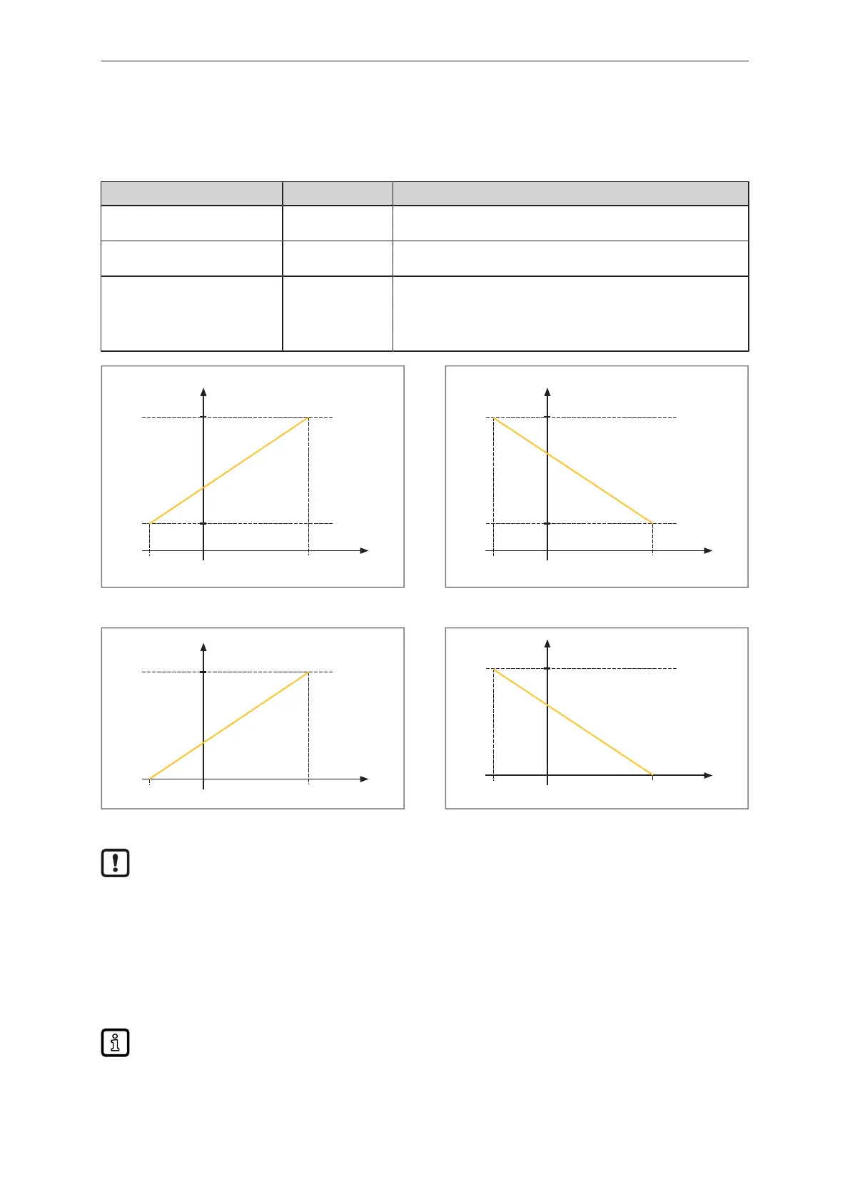
9.3.4 Analogue output
Menu Description
[ASP3] [ASP3] Analogue start point. This value refers to the start point of the con-
figuration of analogue output [ou3].
[AEP3] [AEP3] Analogue end point. This value refers to the end point of the config-
uration of analogue output [ou3].
[dAA3] [dAA3] Damping of the analogue output. Filters out the peaks and the fluc-
tuations in the signal. Behaves like an RC element. If the process
value jumps, the analogue output reaches 63% of the target value
after the configured time. The analogue output reaches the target
value after five times the set time.
PDV
4,0
AEP3
[mA]
ASP3
20,0
Fig.20: Non-negated output, [ou3] = I
PDV
4,0
AEP3
[mA]
ASP3
20,0
Fig.21: Negated output, [ou3] = InEG
PDV
0,0
AEP3
[V]
ASP3
10,0
Fig.22: Non-negated output, [ou3] = U
PDV
0,0
AEP3
[V]
ASP3
10,0
Fig.23: Negated output, [ou3] = UnEG
The source is always MDC 1.
9.3.5 Configuration of the switching outputs
The device provides digital switching signals via switching signal channels (SSC = Switching Signal
Channel).
The device has two digital switching signal channels SSC1.1 and SSC1.2 which can be used to output
the process value.
Explanation of the numbering of the switching channels SSC1.x:
x = switching channel
The switching channels can be analysed via the IO-Link interface and the hardware outputs.
The parameters for each switching signal channel can be set individually.
Bekijk gratis de handleiding van IFM DW3003, stel vragen en lees de antwoorden op veelvoorkomende problemen, of gebruik onze assistent om sneller informatie in de handleiding te vinden of uitleg te krijgen over specifieke functies.
Productinformatie
| Merk | IFM |
| Model | DW3003 |
| Categorie | Niet gecategoriseerd |
| Taal | Nederlands |
| Grootte | 2679 MB |


