Icom IC-FR5100 handleiding
Handleiding
Je bekijkt pagina 6 van 16
3
1
PANEL DESCRIPTION
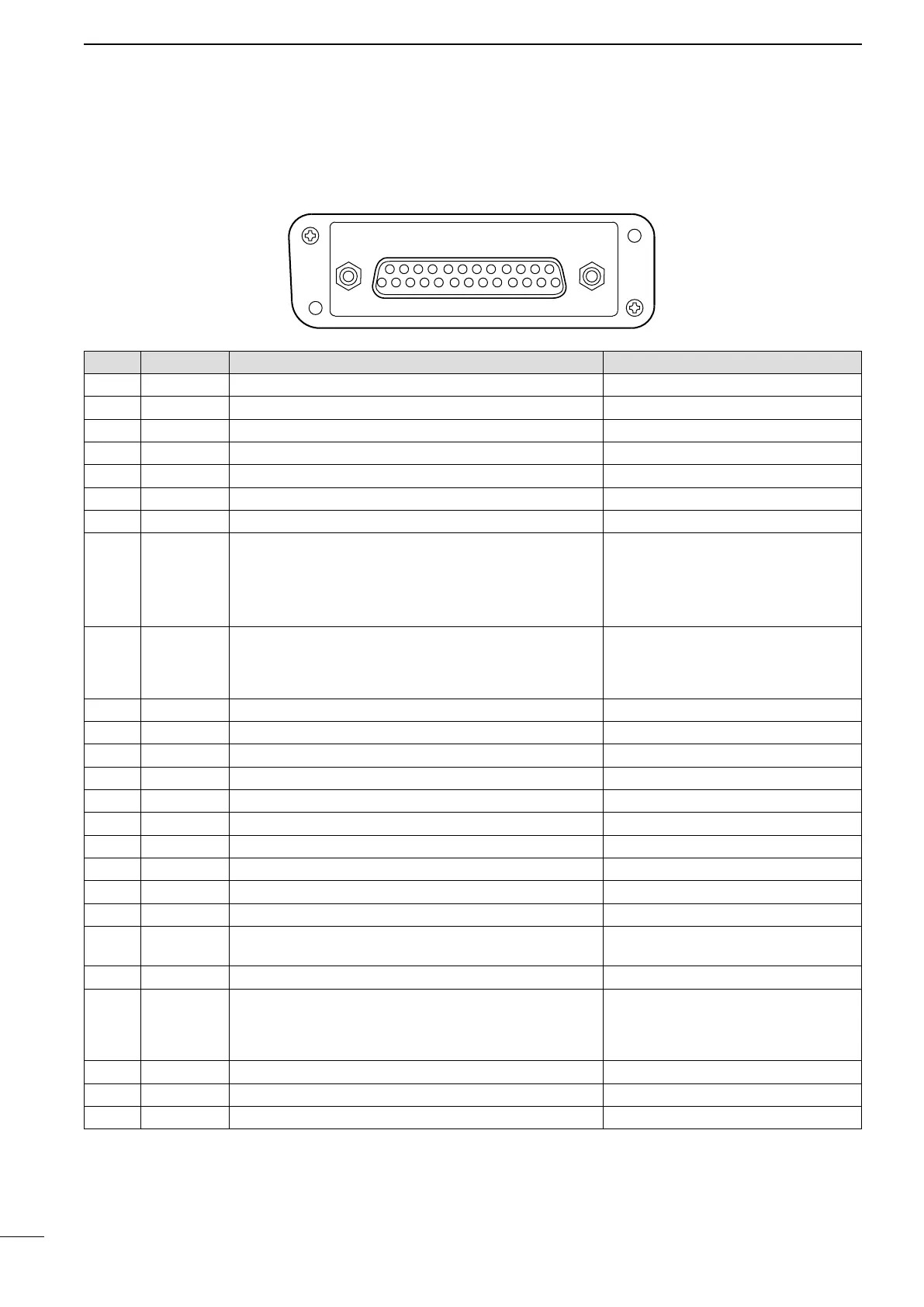
D Accessory connector
q!3
!4 @5
■ Rear panel (Continued)
Pin No. Pin Name Description Specification
1 NC No connection —
2 TXD Output terminal for serial communication data. —
3 RXD Input terminal for serial communication data. —
4 RTS Output terminal for request-to-send data. —
5 CTS Input terminal for clear-to-send data. —
6 NC No connection —
7 GND Serial/digital signal ground —
8 MOD IN
Modulator input from an external terminal unit. Input impedance: 2.7 kΩ
Input level: 85 mV rms (for 60% deviation)
NOTE: If the input impedance is changed
to 27 kΩ, a 300 mV rms input level is
needed for 60% deviation signal.
9 DISC OUT
Buffer output terminal for AF signals from the AF detector
circuit. The output level simultaneously changes with the
modulation level of the received signal, regardless of the
[AF] control setting.
Output level: 300 mV rms*
2
*
2
Received 60% deviation signal
10 EXT. D/A The desired function can be assigned.*
1
—
11 VCC 13.2 V DC output Output current: Less than 1 A
12 EXT. A/D Customize A/D input —
13 NC No connection —
14 GND Ground —
15 EXT. I/O 15 The desired function can be assigned.*
1
+5 V pull up, Active=L*
3
16 EXT. I/O 16 The desired function can be assigned.*
1
+5 V pull up, Active=L*
3
17 EXT. I/O 17 The desired function can be assigned.*
1
+5 V pull up, Active=L*
3
18 EXT. I/O 18 The desired function can be assigned.*
1
+5 V pull up, Active=L*
3
19 EXT. I/O 19 The desired function can be assigned.*
1
+5 V pull up, Active=L*
3
20 DATA I N
Input terminal for data. The signals from this terminal bypass
the pre-emphasis circuit.
Input impedance: 47 k
Ω
Input level: 300 mV rms (for 60% deviation)
21 EXT. I/O 21 The desired function can be assigned.*
1
+5 V pull up, Active=L*
3
22 AF OUT
Buffer output terminal for AF signals through the de-
emphasis circuit from the AF detector circuit. The output
level simultaneously changes with the modulation level of
the received signal, regardless of the [AF] control setting.
Output level: 300 mV rms*
4
*
4
Received 60% deviation signal
23 EXT. I/O 23 The desired function can be assigned.*
1
+5 V pull up, Active=L*
3
24 EXT. I/O 24 The desired function can be assigned.*
1
+5 V pull up, Active=L*
3
25 EXT. I/O 25 The desired function can be assigned.*
1
+5 V pull up, Active=L*
3
*
1
The desired function can be assigned using the optional CS-FR5000(dPMR) cloning software. Ask your dealer for details.
The default settings are shown to the right.
*
3
The active logic can be set to High using the optional CS-FR5000(dPMR) cloning software. Ask your dealer for details.
Bekijk gratis de handleiding van Icom IC-FR5100, stel vragen en lees de antwoorden op veelvoorkomende problemen, of gebruik onze assistent om sneller informatie in de handleiding te vinden of uitleg te krijgen over specifieke functies.
Productinformatie
| Merk | Icom |
| Model | IC-FR5100 |
| Categorie | Niet gecategoriseerd |
| Taal | Nederlands |
| Grootte | 2186 MB |


