Icom IC-7760 handleiding
Handleiding
Je bekijkt pagina 93 van 100
13-4
BASIC MANUAL
CONNECTOR INFORMATION
13
13
D [MIC]
Controller
D [EXT-DISPLAY]
Connect an external display
monitor to mirror the Main
screen.
Outputs the digital RGB signal.
L Set the external display settings in the following item.
MENU
»
SET > Display > External Display
D [RF DECK]
Connect to the RF deck with the supplied
control cable or through a network.
About the LED indication
• When connecting to [CONTROLLER] on the RF
deck:
1 LINK/ACT
- Lights green when a cable is connected.
- Does not light when a cable is not connected.
- Blinks green while communicating.
2 - Lights green when a cable is connected.
- Does not light when a cable is not connected.
• When connecting to a network:
1 LINK/ACT
- Lights green when a cable is connected.
- Does not light when a cable is not connected.
- Blinks green while communicating.
2 Speed
- Lights green while communicating in
1000BASE-T.
- Does not light while communicating in
10BASE-T/100BASE-TX, or when a cable is
not connected.
NOTE: Pin 1 outputs 8 V DC power for Icom
microphones.
L You can turn OFF the DC power when you use non-
Icom microphones the following item.
MENU
»
SET > Connectors > MIC Input DC Bias
Pin No. Description
1
Microphone input
2
+8 V DC output (Maximum 10 mA)
3
Frequency up/down
4
Grounded when squelch opens.
5
PTT*
6
PTT ground
7
Microphone ground
8
AF output (varies with the AF control.)
* To output SEND signal from the PTT pin, set “PTT Port
Function” to “PTT Input + SEND Output.”
MENU
»
SET > Connectors > PTT Port Function
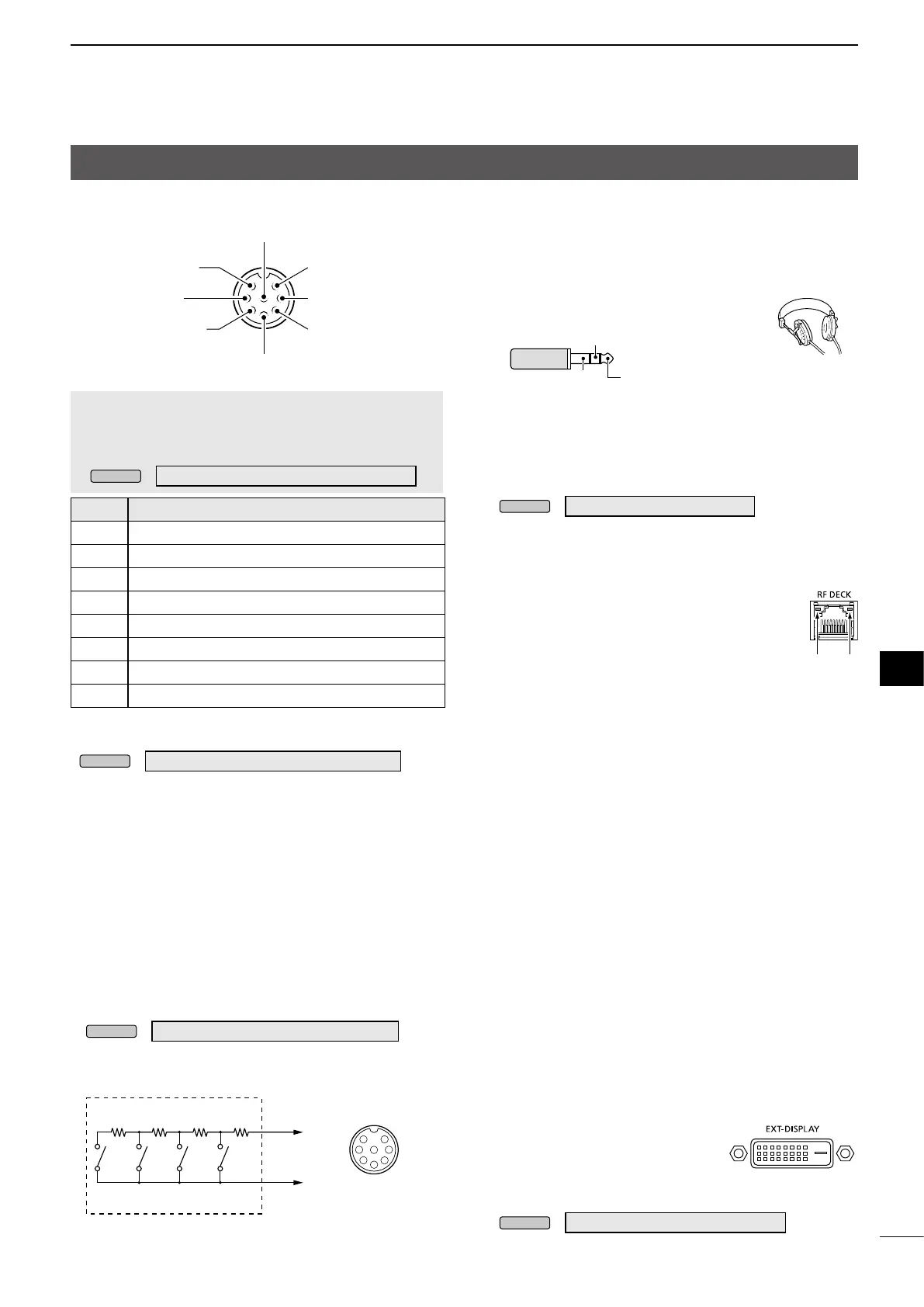
By connecting an external keypad to [MIC] with a
circuit as shown below, you can send the content from
one of 4 memories. You can send the content from
a CW Keyer Memory (M1 ~ M4), SSB/AM/FM Voice
Memory (T1 ~ T4), RTTY Memory (RT1 ~ RT4), or
PSK Memory (PT1 ~ PT4) to be transmitted.
z Push a switch to send the memory content.
z Hold down the switch for 1 second to repeatedly
send the memory content.
L To use the external keypad, turn ON the following item.
MENU
»
SET > Connectors > External Keypad
L The external keypad shown below is not supplied by
Icom.
8 AF output
7 GND
(Microphone ground)
6 GND (PTT ground)
5 PTT
4 Squelch line output
1 Microphone input
2 +8 V DC output
3 Frequency up/down
1.5 kΩ
±5%
1.5 kΩ
±5%
2.2 kΩ
±5%
4.7 kΩ
±
5%
S1S2S3S4
1
2
3
4
5
6
7
8
MIC
External Keypad
Pin 3
Pin 6
[MIC] Connector
Front panel view
1 2
D [PHONES]
Connect to standard stereo headphones:
• Output impedance: 8 ~ 16 Ω
• Output level: More than 5 mW (8 Ω load)
L While headphones are connected, both the internal and
external speakers are deactivated.
L If you use headphones with high impedance, the output
audio may be too loud.
L You can change the output setting in the following item.
MENU
»
SET > Connectors > Phones
3.5 mm (1/8 inch)
Main band signalGND
Sub band signal
(DVI-D)
Bekijk gratis de handleiding van Icom IC-7760, stel vragen en lees de antwoorden op veelvoorkomende problemen, of gebruik onze assistent om sneller informatie in de handleiding te vinden of uitleg te krijgen over specifieke functies.
Productinformatie
| Merk | Icom |
| Model | IC-7760 |
| Categorie | Niet gecategoriseerd |
| Taal | Nederlands |
| Grootte | 18538 MB |


