Helios MiniVent M1/120 handleiding
Handleiding
Je bekijkt pagina 25 van 48
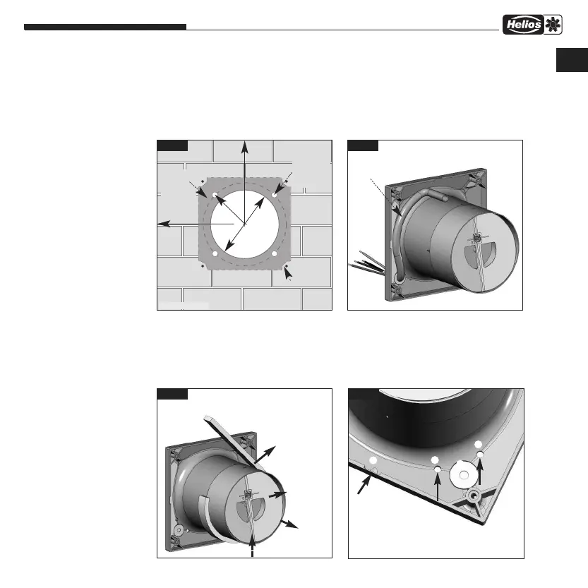
– Duct inside diameter M1/100 = 100 mm or M1/120 = 120 mm
and distance to room corners: at least 90 mm.
– With regard to surface mounted cabling, the side entry knockout for the cable (fig.9, Pos
➀
) in the casing must be
broken out!
– The connection cable and the control line must be stored so that no water can get in along the cable in case of wa-
ter exposure. The cables must not be placed over sharp edges!
2. Drill holes:
Set casing against the wall, mark the holes and drill. Fasten with at least 2 screws and plugs.
3. Back draught shutter and guide van
– When installing the device, the guide vane must be mounted vertically (fig. 8).
Snaps into place every 90° rotation.
– Affix the rubber foam (scope of delivery) before final assembly (fig.8)
MiniVent M1/100/120
Installation and Operation Instructions
7
fig.6
Ø
100
mm
Ø
12
0
m
m
*
r=58 m
m
r=68 m
m
*
min. 90 mm
min. 90 mm
C
able exit
possible as
required in
dark area
drill holes
Recommen-
ded cable
exit optional
0...-360 °,
ideally 45°
fig.7
Cable routing under the casing. Cable
length from wall at least
180 mm.
* Type M1/120..
fig.8
When installing the device, the gui-
de vane
➎ must be mounted verti-
cally (as depicted). Snaps into place
every 90° rotation.
Guide vane ➎
removable
Back dr-
aught
shutter
➏
removable
➎
Affix the rub-
ber foam
vertical for wall installation
top
bottom
fig.9
➁
Condensate drain holes for
ceiling suspension.
➀
➀ Break out entry
knockout for cable for
wall mounting
➁
➂
➁
UK
Bekijk gratis de handleiding van Helios MiniVent M1/120, stel vragen en lees de antwoorden op veelvoorkomende problemen, of gebruik onze assistent om sneller informatie in de handleiding te vinden of uitleg te krijgen over specifieke functies.
Productinformatie
| Merk | Helios |
| Model | MiniVent M1/120 |
| Categorie | Ventilator |
| Taal | Nederlands |
| Grootte | 5307 MB |