Growatt WIT 50-100KTL3-AU handleiding
Handleiding
Je bekijkt pagina 20 van 66
3. Crimp the battery cables and the battery terminals using crimping pliers, and then
tighten the insulation sleeve;
2. Strip 18-20 mm of the insulation layer of the DC cables;
1. Connect the ground cable to the battery power ground bar, as shown in Fig 6.6;
5. After connecting the main battery power cables, bind power cables at the reserved
position, as shown in Fig 6.6.
4. Connect the battery cables to the battery terminals on the inverter, as shown in Fig 6.6;
Procedure for connecting the main battery power:
Fig 6.6 Position of the battery terminals
Route the cable
Strip the cable
19±1mm
Tighten the terminal
Connect to the terminal
Tighten the clamp
1
2
3
4
5
6
Crimp the cable
NOTE:
2. Bind the battery power cables at the designated place after connecting them to the WIT
Inverter.
3. Lock the right cover plate after connecting the cables.
1. Connect the ground cable before connecting the battery cable; the ground point is
shown in Fig 6.6.
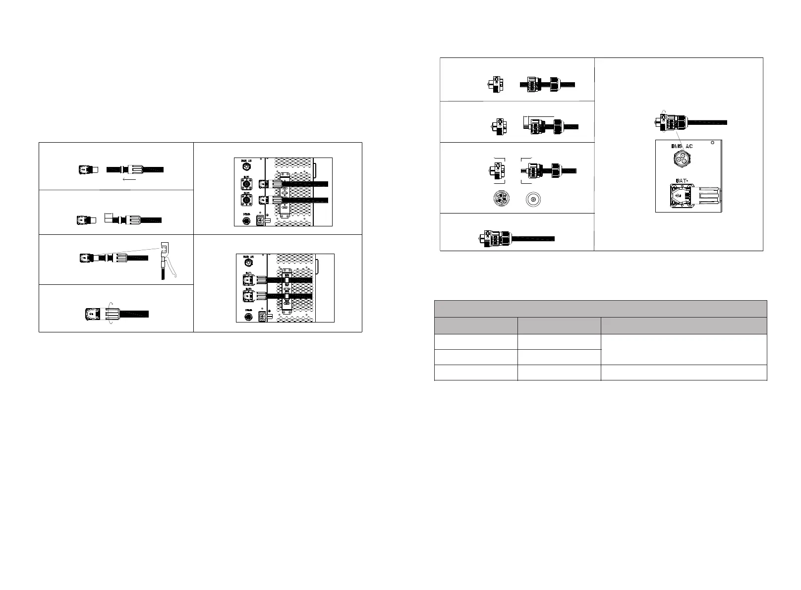
6.4.2 Connecting the Battery BMS-AC Terminal
NOTE: Perform operations according to on-site requirements.
3. Remove the dustproof cover from the BMS-AC terminal, insert the terminal that has
been crimped with the cables to the BMS-AC terminal, and tighten it.
Procedure for connecting the battery BMS-AC terminal:
1. Open the cover plate on the right side of the inverter, the position of which is shown in
Fig 6.6;
2. Find the corresponding terminal from the accessory kit. Refer to Table 6.3 to connect
the terminal;
Fig 6.7 BMS-AC termina
Secure the cable
1
2
3
4
5
Route the cable
Strip the cable
11±1mm
A
A
B
B
A-A
B-B
Tighten the terminal
Connect to the terminal
Table 6.3 Definitions of BMS-AC terminal
BMS-AC terminal port definition
Number
Definition of signal
Note
1
L
Supply power to the BMS
2
N
3
PE
Grounding
2. Reinstall the battery protective plate and the right cover plate after the cable
connection is completed.
1. Do not touch or remove the dustproof cover if the BMS-AC terminal is idle.
NOTE:
6.5 Connecting Communications Cables
6.5.1 Battery Communication Connection
The BMS-COM terminal of the WIT 50-100K Inverter is a 16-pin connector. The matching
male terminal are delivered with the package.
1. Connect the communication cables to the corresponding terminals as required. For
details, see Table 6.4;
2. Remove the dustproof cover from the BMS-COM terminal, insert the 16-pin terminal
(the client side) to the corresponding position, and ensure that it is tightly connected;
33
34
Bekijk gratis de handleiding van Growatt WIT 50-100KTL3-AU, stel vragen en lees de antwoorden op veelvoorkomende problemen, of gebruik onze assistent om sneller informatie in de handleiding te vinden of uitleg te krijgen over specifieke functies.
Productinformatie
| Merk | Growatt |
| Model | WIT 50-100KTL3-AU |
| Categorie | Niet gecategoriseerd |
| Taal | Nederlands |
| Grootte | 14891 MB |


