Growatt WIT 50-100KTL3-AU handleiding
Handleiding
Je bekijkt pagina 19 van 66
1. Open the right cover plate of the WIT inverter, the position of which is shown in Fig 6.1;
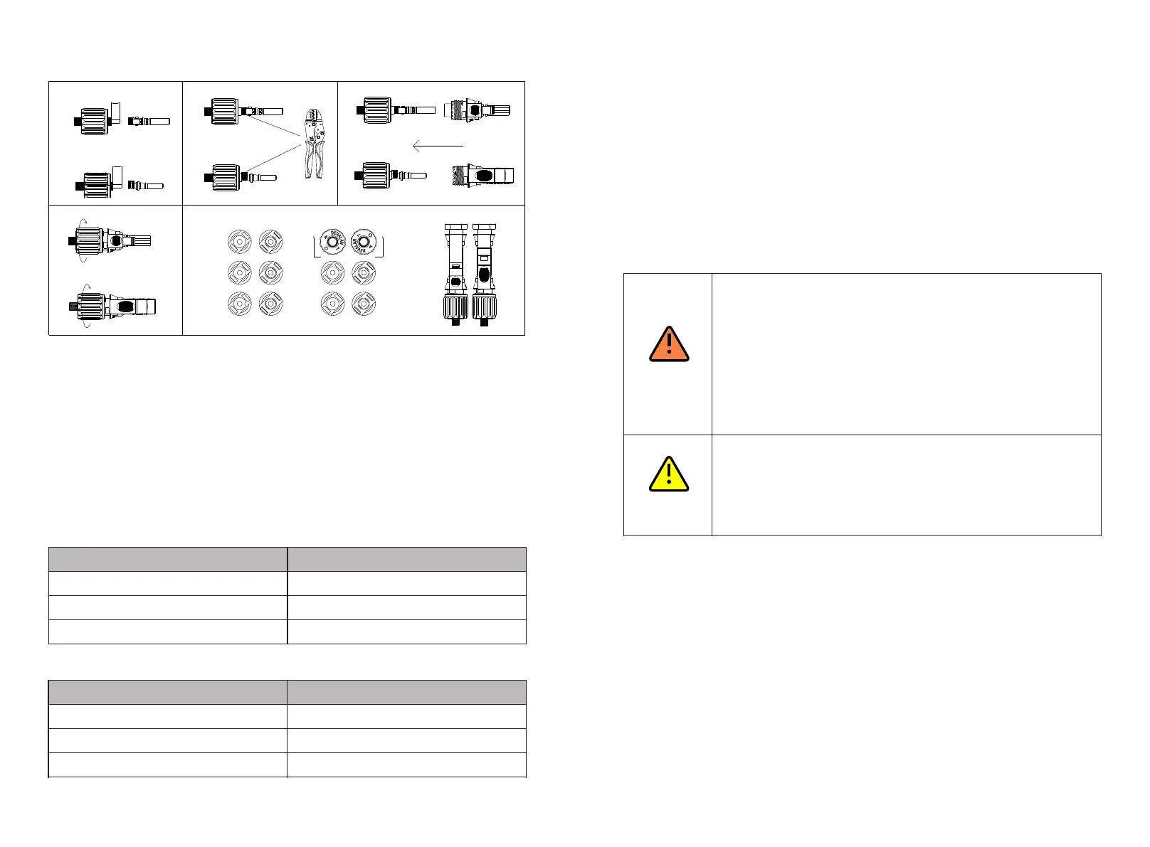
Procedure for connecting cables on the PV side:
2. Strip 6-8 mm of the insulation layer of the DC cables.
3. Insert the exposed core wires into the crimping area of the wiring terminal and crimp
them using a crimping plier;
4. Route the cable through the cable sealing sleeve and insert the insulation sleeve until it
snaps. Slightly pull the cable back to ensure that it is securely connected. Then tighten
the locking nut;
5. Insert the positive and negative connectors of the PV modules to the corresponding
terminals of the inverter. For the maximum input current of different models, please see
Table 6.1. For the cable specifications, please see Table 6.2.
Table 6.1 Maximum current of a single MPPT route
Device type
Max. current of a single MPPT route
WIT 50-100K-H
16A*2
WIT 50-100K-HE
16A*2
WIT 50-100K-HU
16A*2
Table 6.2 Cable specifications on the PV side
Device type
Recommendation cable specifications
WIT 50-100K-H
2
4-6mm
WIT 50-100K-HE
2
4-6mm
WIT 50-100K-HU
2
4-6mm
NOTE:
4. Do not touch the solar panels in operation;
2. Use male and female connectors in pair. Ensure the correct polarity before connecting
the PV string to the inverter.
1. For a single WIT Inverter, connect the ground cable of the inverter. For a system with
multiple WIT Inverters connected in parallel, connect the ground cables of all inverters
and the metal racks of the PV modules to the same area to ensure equipotential
bonding. Before connecting the PV cables, ensure that the ground cables on the PV side
are properly connected.
3. The total current of all strings cannot exceed the WIT Inverter's maximum input current;
5. The wires should be tinned and are not frayed or cracked.
31
6.4 Connection on the Battery Side
Ÿ Please do not place inflammable and explosive materials around the
WIT Inverter.
Ÿ Before connecting cables, ensure that the DC switches of the WIT
Inverter are OFF, and turn off the breakers on the AC side and the
battery side. Otherwise, the high voltages of the WIT Inverter may
cause electric shocks.
Ÿ Only qualified and trained electrical technicians are allowed to
perform operations. Technicians must observe instructions in this
manual and local regulations.
Ÿ High voltages may cause electric shocks and serious injury. Please do
not touch the inverter in operation.
Ÿ If the cable is thick, do not shake the cable after fastening it. Ensure
that all cables are securely connected before powering on the WIT
Inverter. Loose connection may cause overheating that will damage
the device.
6.4.1 Connecting the Main Power Cable of the Battery
4. Open the cover plate on the right side of the inverter, the position of which is shown in
Fig 6.1.
Preparation:
1. Check that the battery terminals of the WIT Inverter are intact;
2. Disconnect the DC switches on the WIT inverter, the AC breaker and the DC switch on
the battery;
3. Take out the battery terminals from the accessory kit delivered with the package. See
Packing list in Section 4;
7mm
7mm
1
2
3
4
A-A
A
A
5
Fig 6.5 PV terminals
1. The recommended battery voltage range is 600V to 1000V.
2. You are advised to install a DC circuit breaker between the battery and the WIT inverter.
Note:
32
DANGER
WARNING
Bekijk gratis de handleiding van Growatt WIT 50-100KTL3-AU, stel vragen en lees de antwoorden op veelvoorkomende problemen, of gebruik onze assistent om sneller informatie in de handleiding te vinden of uitleg te krijgen over specifieke functies.
Productinformatie
| Merk | Growatt |
| Model | WIT 50-100KTL3-AU |
| Categorie | Niet gecategoriseerd |
| Taal | Nederlands |
| Grootte | 14891 MB |


