Growatt WIT 50-100KTL3-AU handleiding
Handleiding
Je bekijkt pagina 18 van 66
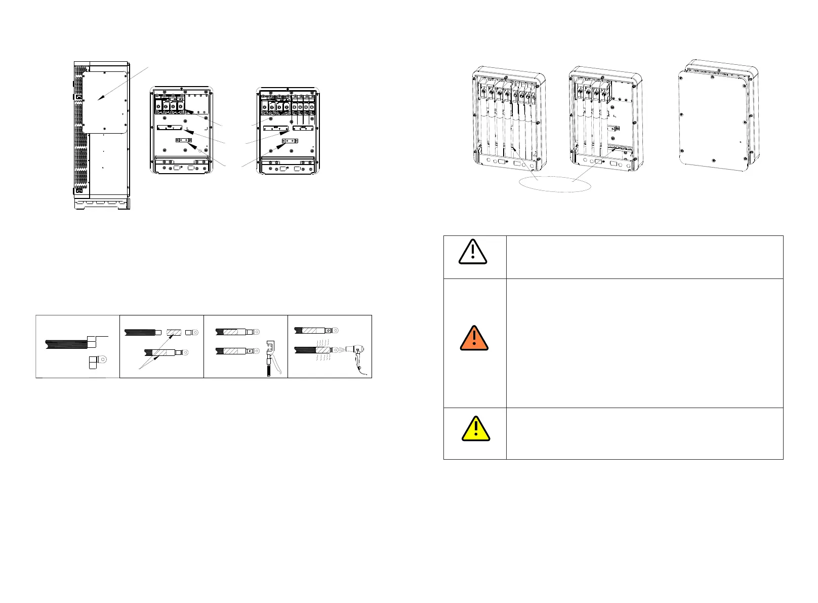
Fig 6.2 AC terminal wiring position and diagram
NOTE:
1. The waterproof silicone pad is used to protect the lower side of a terminal box. Cut
holes in the pad according to the outer diameter of the cables to route them through.
After routing through the cables, determine the cable stripped length based on the
specifications of the terminals (18-22 mm is recommended). Crimp the cables and the
terminals. See Figure 6.3 for crimping a cable;
Fig 6.3 Crimping a cable
have an additional type of terminal in the AC junction box compared with WIT 50-
2. Cold-pressed terminals are delivered with the package. Select terminals based on the
cable specifications;
3. WIT 50-100K-AE, WIT 50-100K-HE, WIT 50-100K-AU and WIT 50-100K-HU models
100KA and WIT 50-100K-H models. Connect cables according to the label;
4. After connecting the cables, apply fireproof mud to the waterproof silicone mat at the
inlet side. Lock the cover of the AC junction box after the fireproof mud is applied. See
Fig 6.4 below.
Fig 6.4 Applying fireproof mud
PE
Lable
AC
Terminal
AC junction
box cover
-A/-H AC
junction box
-AE/-AU/-HE/-HU
AC junction box
6.3 Connection on the PV Side
Ÿ Only WIT 50-100K-H, WIT 50-100K-HE and WIT 50-100K-HU models
need to be connected on the PV side.
Ÿ Before connecting cables, ensure that the DC switches of the WIT
Inverter are OFF, and turn off the breakers on the AC side and the
battery side. Otherwise, the high voltages of the WIT Inverter may
cause electric shocks.
Ÿ Only qualified and trained electrical technicians are allowed to
perform operations. Technicians must observe instructions in this
manual and local regulations.
Ÿ Check the positive and negative terminals for the correct polarity
before connecting the PV module to the WIT Inverter.
Ÿ Please do not place inflammable and explosive materials around the
WIT Inverter.
Ÿ High voltages may cause electric shocks and serious injury. Please do
not touch the inverter in operation.
Ÿ The maximum open-circuit voltage of each string should not exceed
1100Vdc.
Ÿ Ensure that the following conditions are met; Otherwise, fire hazard
or inverter damage may occur. Growatt is not liable for the
consequence and it is beyond the warranty scope.
NOTE:
4. The power of the PV panels should not exceed twice the input power of the WIT Inverter.
2. The PV modules connected in series should be of the same model.
1. The solar irradiance on the PV modules generates voltage. High voltages presented in
the PV strings connected in series could be fatal. Therefore, shield the PV modules from
sunlight before connecting the DC input power cable and ensure that the DC switches
on the WIT Inverter are OFF.
3. The maximum short-circuit current of each PV string must be lower than or equal to 40A.
5. For optimal system configuration, it is recommended to connect two DC inputs with an
equal number of PV modules.
29
E
L=E+2mm
Heat shrink tubing
1
2
3
4
fireproof mud
30
NOTICE
DANGER
WARNING
Bekijk gratis de handleiding van Growatt WIT 50-100KTL3-AU, stel vragen en lees de antwoorden op veelvoorkomende problemen, of gebruik onze assistent om sneller informatie in de handleiding te vinden of uitleg te krijgen over specifieke functies.
Productinformatie
| Merk | Growatt |
| Model | WIT 50-100KTL3-AU |
| Categorie | Niet gecategoriseerd |
| Taal | Nederlands |
| Grootte | 14891 MB |


