Garrett Paragon handleiding
Handleiding
Je bekijkt pagina 36 van 44
36 1557900 REV B 1 Garrett Metal Detectors
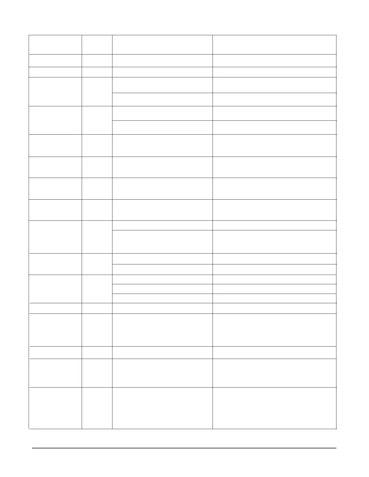
Maintenance / Troubleshooting
Failure
Message
Motion Sensor Fail
No Line Sync
Power Mod Fail
No Leader
DSP Fail
Invalid TX Freq
Please Correct
AC Sync Fail
NO
NO
YES
NO
YES
NO
NO
Critical
Failure
Possible Failures
Panel B Cable connection at panel
Panel B connector at PCB P7
Power Mod failure
Controller PCB failure
Power supply connection at P1
Defective power supply
No wireless or wired leader available
Bad Controller PCB
Invalid frequency range (between
0-1969) with Multi-Unit Role value of
"Leader" or "Follower"
AC cord connection
Power supply connection to PCB
Orange and White wire connection to
PCB
Power Supply failure
Controller PCB failure
Remedy
Insert connector rmly. Replace cable.
Insert connector rmly. Replace cable.
Replace
Replace
Insert connector rmly.
Replace Power Mod
Switch on designated Leader. Verify that Group
Leader and the Follower frequencies are the same
for wireless sync.
Verify wire connections for wired sync.
Replace Controller PCB
Change Multi-Unit Role value to "Solo" or
change Frequency to value between 1970-2300
Check AC cord connected rmly on both ends.
Check that connector is rmly seated to PCB.
Replace Power Suppy rst.
Replace controller PCB.
FIGURE 9-1
Transmitter O
Transmitter O
Transmitter Fail
Receiver A Zone*
Peak Fail
Transmitter Fail
Receiver B Zone*
Peak Fail
Receiver B Zone 5-8
Peak Fail
Receiver B Zone 1-4
Peak Fail
Receiver A Zone 5-8
Peak Fail
Receiver A Zone 1-4
Peak Fail
Receiver Saturation
YES
NO
YES
YES
YES
YES
YES
YES
YES
Transmitters A and B switched O
Transmitter A or B switched O
Panel A Cable connection at panel
Panel A Cable connection at PCB P7
Panel B Cable connection at panel
Panel B Cable connection at PCB P8
Panel B Cable connection at PCB P10
Panel B Cable connection at PCB P9
Panel B Cable connection at PCB P5
Panel B Cable connection at PCB P4
Very large object near panel.
Interference from nearby metal detector.
Switch On using the Administrator Menu Option
Switch On using the Administrator Menu Option
Insert connector rmly. Replace cable.
Insert connector rmly. Replace cable.
Insert connector rmly. Replace cable.
Insert connector rmly. Replace cable.
Insert connector rmly. Replace cable.
Insert connector rmly. Replace cable.
Insert connector rmly. Replace cable.
Insert connector rmly. Replace cable.
Remove large metal object.
Switch o nearby metal detectors, increase distance
between detectors. ensure proper multi-unit
synchronization.
See gure 5-6 for connection locations.
Bekijk gratis de handleiding van Garrett Paragon, stel vragen en lees de antwoorden op veelvoorkomende problemen, of gebruik onze assistent om sneller informatie in de handleiding te vinden of uitleg te krijgen over specifieke functies.
Productinformatie
| Merk | Garrett |
| Model | Paragon |
| Categorie | Niet gecategoriseerd |
| Taal | Nederlands |
| Grootte | 6746 MB |