Extron FOX II T HD 4K handleiding
Handleiding
Je bekijkt pagina 14 van 41
FOX II T HD 4K Transmitter • Installation and Operation 6
A
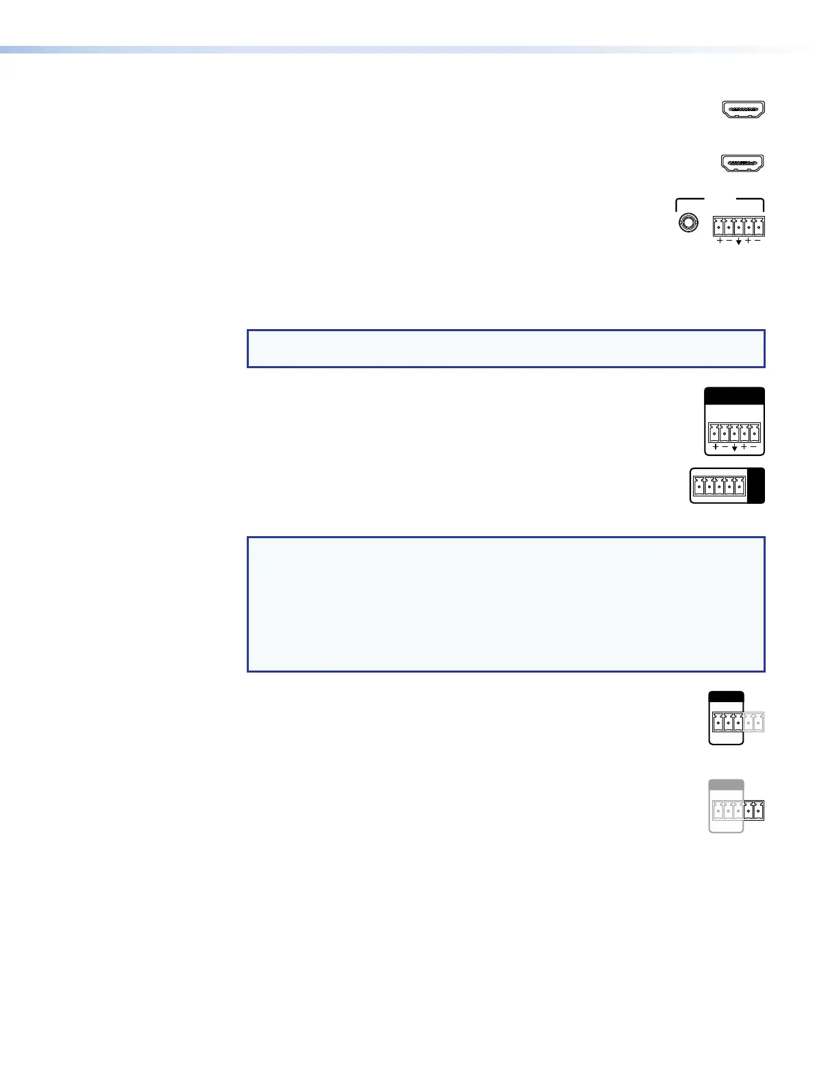
HDMI input port (see figure 2 on the previous page) — Connect a digital
HDMI
video input to this HDMI connector. The transmitter also accepts embedded
digital audio on this connector.
B
Loop-through port — If desired, connect a local monitor to this HDMI
LOOP THRU
connector.
C
Analog audio input ports — These connectors accept the analog,
LR
AUDIO
unamplified, line level audio input that can be transmitted to the
receiver (see Audio connections on page 9 to wire these
connectors).
TRS connector — Plug an unbalanced audio input into this stereo TRS connector.
Captive screw input connector — Connect a balanced or unbalanced audio input to
this 3.5 mm, 5-pole captive screw connector.
NOTE: If both the TRS and captive screw audio connector are connected, the TRS
takes priority.
D
Audio Return Out port — Connect an audio device, such as an amplifier
LR
AUDIO
RETURN OUT
or powered speakers to this 5-pole, 3.5 mm captive screw connector. This
connector outputs returned, unamplified, line level audio from the receiver
(see Audio connections on page 9 to wire this connector).
E
Over Fiber RS-232 and IR port — Connect a serialRS-232 signal, a
RS-232 IR
Tx Rx Tx RxG
OVER
FIBER
modulated or unmodulated IR signal, or both to this 3.5 mm, 5-pole
captive screw connector for bidirectional RS-232 and IR communication.
See RS-232 and IR connections on page 9 to wire the connector.
NOTES:
• If you connect only one fiber optic cable (see item
H
, on the next page), you
will not receive RS-232 or IR reports from the controlled device. To receive
responses from the controlled device, you must install two fiber optic cables.
•
The FOX II T HD 4K can pass RS-232 commands and r
esponses at rates up to
115200 baud.
• RS-232 and IR can be active simultaneously.
F
Remote RS-232 port — For serial control of the transmitter, connect a
RS-232
ALAR
M
Tx Rx G
12
REMOTE
host device, such as a computer or touch panel control, via the three
leftmost poles (Tx, Rx, and G) of this 5-pole captive screw connector (see
RS-232 and IR connections on page 9 to wire this connector). See
Remote Control on page 14 for SIS commands.
G
Alarm port — For remote monitoring of the status of the Rx fiber optic link
RS-232
ALARM
Tx Rx G
12
REMOTE
(the optional fiber cable), connect an external control system or a locally-
constructed or furnished monitoring device to the transmitter via the two
rightmost poles (1 and 2) of this 5-pole captive screw connector. When the
transmitter does not detect a light link on fiber cable Rx (optional), pin 1 and
pin 2 of this port are shorted together (see Alarm connection on page 11 to wire this
connector).
Bekijk gratis de handleiding van Extron FOX II T HD 4K, stel vragen en lees de antwoorden op veelvoorkomende problemen, of gebruik onze assistent om sneller informatie in de handleiding te vinden of uitleg te krijgen over specifieke functies.
Productinformatie
| Merk | Extron |
| Model | FOX II T HD 4K |
| Categorie | Niet gecategoriseerd |
| Taal | Nederlands |
| Grootte | 5917 MB |


