Eura VDP-45A3 Alpha handleiding
Handleiding
Je bekijkt pagina 5 van 40
EN 5
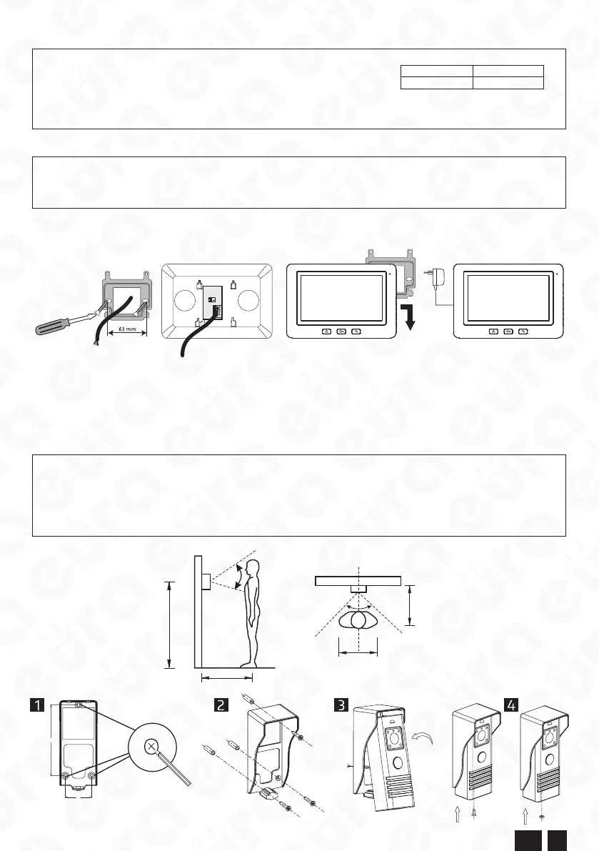
2. SYSTEM INSTALLATION
NOTE:
Recommended cross sections of wires connecting both modules depending on the distance between them:
0 - 50m 4x0.5mm
2
50m - 100m 4x0.75mm
2
The connection to the electromagnetic bolt should be made with a 2x0.75mm
2
wire. The optimum solution will be to use one 4-core wire to connect the
monitor to the outdoor box, one 2-core wire to connect the outdoor module to the electromagnetic bolt. If the user’s connection wires are different from the
recommended wires, it is permissible to use them, however a test connection of the system is required to check it for proper operation.
2.1. OUTDOOR MODULE (MONITOR) INSTALLATION
NOTE
It is recommended to screw the monitor installation frame to a previously seated Ø60 mm ush mounting box.Improper attachment of the installation
frame could have an adverse impact on proper operation of the monitor. Avoid suspending the monitor to the frame by force. The ush mounting box is
not included.
1. Screw the included mounting frame (g. 3a) of the module to the wall/ush mounting box so as to enable easy and clean routing of the system connection wire
and power supply wire. The standard height, at which the centre of the monitor should be placed aer suspending to the frame is approx. 145 cm, however it can
be positioned according to the individual user needs.
12
3
4
a
c
d
b
Fig. 3
2. Connect the individual wire cores to the connection terminals in the rear of the monitor (g. 3b) according to the diagram (g. 6).
3. Connect the included power supply plug to the power supply unit outlet (g. 1).
4. The rear part of the monitor enclosure features 4 openings (g. 1) used to suspend this module to the installation frame. Gently suspend the monitor to the frame
according to the direction indicated by the arrow in g. 3c so that all 4 frame brackets are in the openings in the enclosure.
5. Connect the power supply unit to the ~230V/50Hz mains.
2.2. OUTDOOR MODULE (CAMERA) INSTALLATION
The outdoor module is manufactured suitable for surface mounting.
NOTE:
Proper placement of the outdoor camera module determines the comfort of work with the device. Thus, before drilling installation opening, it is recommended
to select the place for installation through testing. For this purpose install the monitor by connecting it (according to the instruction manual) to the camera, which
should be held by another person during the tests. Connect the mains power supply and proceed to the selection of the proper place for installation of the camera.
The person holding the camera shall simulate normal activation of the device by calling the other person, located at the monitor, by pressing the button (g. 2). At
the same time, the person at the monitor shall observe the eld of view of the camera. The person holding the camera module shall set it in the optimum position,
based on the suggestions of the other person. Mark this position and only aerwards proceed to the drilling of installation opening.
50 cm
50
o
50 cm
50 cm
150-160 cm
62
o
Fig. 4
SS
SS
Fig. 5
Bekijk gratis de handleiding van Eura VDP-45A3 Alpha, stel vragen en lees de antwoorden op veelvoorkomende problemen, of gebruik onze assistent om sneller informatie in de handleiding te vinden of uitleg te krijgen over specifieke functies.
Productinformatie
| Merk | Eura |
| Model | VDP-45A3 Alpha |
| Categorie | Niet gecategoriseerd |
| Taal | Nederlands |
| Grootte | 8567 MB |

