Daikin REYA16A7Y1B handleiding
Handleiding
Je bekijkt pagina 39 van 60
17 Electrical installation
Installation and operation manual
39
REMA5+REYA8~20A7Y1B
VRV 5 heat recovery
4P684060-1C – 2024.10
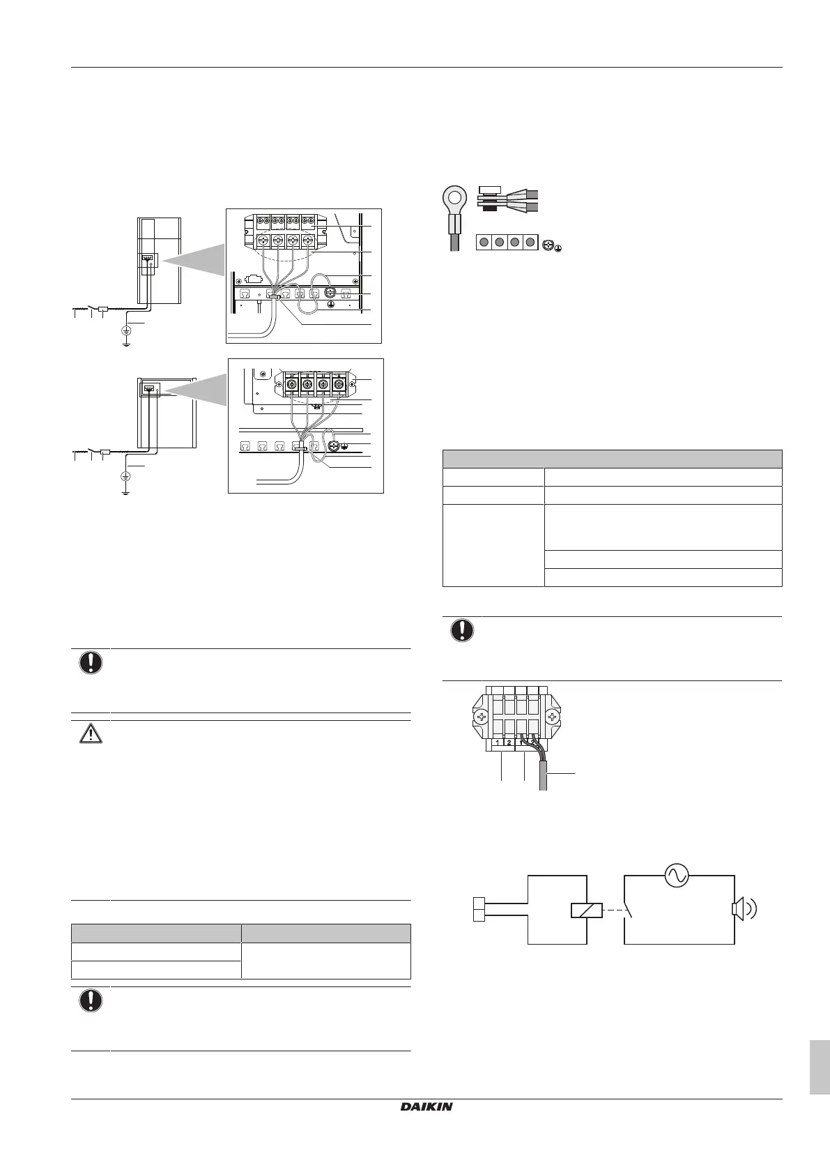
17.7 To connect the power supply
The power supply MUST be clamped to the bracket using field
supplied clamp material to prevent external force being applied to
the terminal. The green and yellow striped wire MUST be used for
earthing only.
See "17.2 Specifications of standard wiring components" [4 37] for
wiring requirements.
5~12 HP
a
bc d
f
g
e
i
j
h
14~20 HP
a
bc d
f
g
e
i
j
h
a Power supply (380~415 V, 3N~50Hz)
b Fuse
c Earth leakage protector
d Earth wire
e Power supply terminal block
f Connect each power wire: RED to L1, WHT to L2, BLK to
L3 and BLU to N
g Earth wire (GRN/YLW)
h Tie wrap
i Cup washer
j When connecting the earth wire, it is recommended to
perform curling.
NOTICE
Never connect the power supply to transmission wiring
terminal block. Otherwise the entire system may break
down.
CAUTION
▪ When connecting the power supply: connect the earth
cable first, before making the current-carrying
connections.
▪ When disconnecting the power supply: disconnect the
current-carrying cables first, before separating the earth
connection.
▪ The length of the conductors between the power supply
stress relief and the terminal block itself MUST be as
such that the current-carrying wires are tautened before
the earth wire is in case the power supply is pulled
loose from the stress relief.
Tightening torque for the terminal screws:
Screw size Tightening torque (N•m)
M8 (power terminal block) 5.5~7.3
M8 (ground)
NOTICE
When connecting the earth wire, align the wire with the cut
out section of the cup washer. Incomplete earthing may
cause electrical shock.
Multiple outdoor units
To connect the power supply for multiple outdoor units to each other,
ring tongues have to be used. No bare cable can be used.
In that case, the ring washer that is installed by default should be
removed.
Attach both cables to the power supply terminal as indicated below:
L1 L2 L3 N
17.8 To connect the external outputs
SVS and SVEO output
The SVS and SVEO outputs are contacts on terminal X2M.
The SVS output is a contact on terminal X2M that closes in case a
leak is detected, failure or disconnection of the R32 sensor (located
in the BS unit or indoor unit).
The SVEO output is a contact on terminal X2M that closes in case of
occurrence of general errors. See "8.1Error codes: Overview"[413]
and "22.1.1 Error codes: Overview" [448] for errors that will trigger
this output.
Outdoor output connection requirements
Voltage 220~240V
Maximum current 0.5A
Wire size Only use harmonised wiring providing double
insulation and suitable for the applicable
voltage.
2-core cable
Minimum cable section of 0.75mm²
NOTICE
Do NOT use the outputs as a power source. Instead, use
each output to energize a relay that controls the external
circuit.
WHT
SVEO SVS
BLK GRY PPL
ba
c
X2M
a SVEO output terminals (1 and 2)
b SVS output terminals (1 and 2)
c Cable to SVS output device (example)
Example:
X2M
(SVS)
a
1
2
c
b d
a SVS output terminal
b Relay
c AC power supply 220~240VAC
d External alarm
Cable routing
Route the SVEO or SVS output cable as indicated below.
Bekijk gratis de handleiding van Daikin REYA16A7Y1B, stel vragen en lees de antwoorden op veelvoorkomende problemen, of gebruik onze assistent om sneller informatie in de handleiding te vinden of uitleg te krijgen over specifieke functies.
Productinformatie
| Merk | Daikin |
| Model | REYA16A7Y1B |
| Categorie | Niet gecategoriseerd |
| Taal | Nederlands |
| Grootte | 10147 MB |


