Daikin REYA16A7Y1B handleiding
Handleiding
Je bekijkt pagina 38 van 60
17 Electrical installation
Installation and operation manual
38
REMA5+REYA8~20A7Y1B
VRV 5 heat recovery
4P684060-1C – 2024.10
X1A
b
5~12 HP 14~20 HP
e
a e
c
d
d
d
d
d
d
a b
e
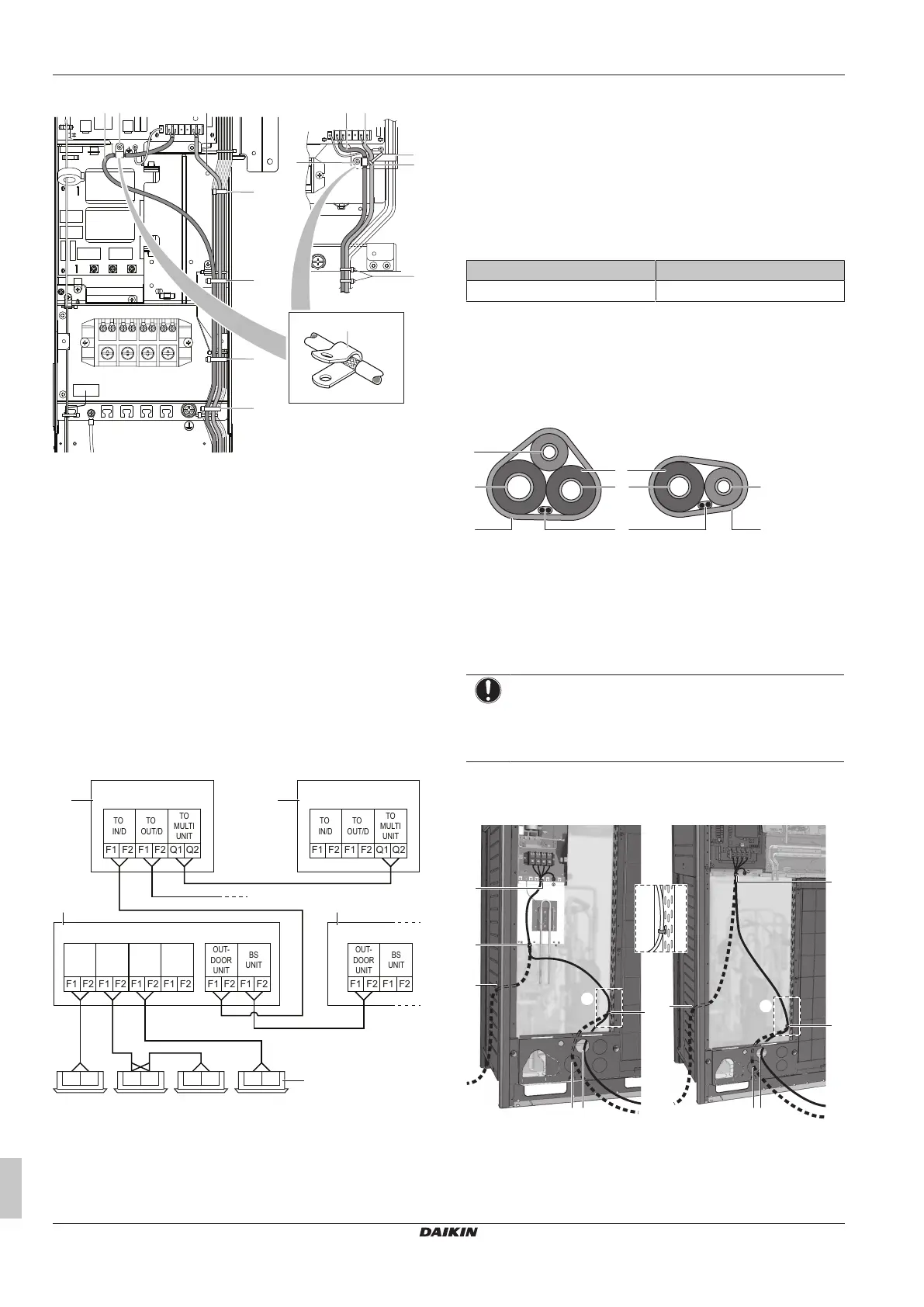
a Wiring between the units (indoor-outdoor) (F1/F2 left)
b Internal interconnection wiring (Q1/Q2)
c Plastic bracket
d Tie wrap (field supply)
e P-clamp for cable shield earthing
Fix to the indicated plastic brackets using field supplied clamping
material.
The indoor F1/F2 interconnection wiring MUST be shielded wire.
The shielding is earthed via a metal P-clamp (e) (only at outdoor
unit). Strip the insulation up to the shielding mesh, to provide full
contact of the earth with the shielding.
17.4 To connect the interconnection
wiring
The wiring from the indoor units must be connected to the F1/F2
(In‑Out) terminals on the PCB in the outdoor unit.
See "17.2 Specifications of standard wiring components" [4 37] for
wiring requirements.
INDOOR
UNIT
A
a
1
INDOOR
UNIT
B
INDOOR
UNIT
C
INDOOR
UNIT
D
OUT-
DOOR
UNIT
BS
UNIT
F1
F2
F1
F2
F1
F2
F1
F2
F1
F2
F1
F2
TO
IN/D
TO
OUT/D
F1
F2
F1
F2
TO
MULTI
UNIT
Q1
Q2
a
2
c
d
TO
IN/D
TO
OUT/D
F1
F2
F1
F2
Q1
Q2
F1 F2 F1 F2 F1 F2F1 F2
OUT-
DOOR
UNIT
BS
UNIT
F1
F2
F1
F2
TO
MULTI
UNIT
b
1
b
2
a1 Unit A (master outdoor unit)
a2 Unit B (slave outdoor unit)
b1 BS unit 1
b2 BS unit 2
c Indoor unit
d Outdoor unit/other system interconnection (F1/F2)
▪ The interconnecting wiring between the outdoor units in the same
piping system must be connected to the Q1/Q2 (Out Multi)
terminals. Connecting the wires to the F1/F2 terminals results in
system malfunction.
▪ The wiring for the other systems must be connected to the F1/F2
(Out-Out) terminals of the PCB in the outdoor unit to which the
interconnecting wiring for the indoor units is connected.
▪ The base unit is the outdoor unit to which the interconnecting
wiring for the indoor units is connected.
Tightening torque for the interconnection wiring terminal screws:
Screw size Tightening torque [N•m]
M3.5 (A1P) 0.8~0.96
17.5 To finish the interconnection
wiring
After installing the interconnection wiring, wrap it along with the
onsite refrigerant piping using finishing tape, as shown in the
illustration below.
d
b
e
a
d
a
c
f
a Liquid piping
b Gas piping
c High pressure / low pressure gas piping
d Finishing tape
e Interconnection cable (F1/F2)
f Insulation
17.6 To route and fix the power supply
NOTICE
When routing earth wires, secure clearance of 25 mm or
more away from compressor lead wires. Failure to observe
this instruction properly may adversely affect correct
operation of other units connected to the same earth.
The power supply wiring can be routed from the front and left side.
Fix it to the lower mounting hole.
c
X1M
aba
c
d
X1M
b
5~12 HP 14~20 HP
A
A
d
d
d
d
A
a Power supply (possibility 1)
(a)
b Power supply (possibility 2)
(a)
c Power supply (possibility 3)
(a)
. Use conduit.
d Tie wrap
(a)
Knockout hole has to be removed. Close the hole to
avoid small animals or dirt from entering.
Bekijk gratis de handleiding van Daikin REYA16A7Y1B, stel vragen en lees de antwoorden op veelvoorkomende problemen, of gebruik onze assistent om sneller informatie in de handleiding te vinden of uitleg te krijgen over specifieke functies.
Productinformatie
| Merk | Daikin |
| Model | REYA16A7Y1B |
| Categorie | Niet gecategoriseerd |
| Taal | Nederlands |
| Grootte | 10147 MB |


