Daikin EKEXVA350 handleiding
Handleiding
Je bekijkt pagina 22 van 36
13 Unit installation
Installation and operation manual
22
EKEACBVE + EKEXVA50~500
Option kit for combination of Daikin outdoor units with field-
supplied air handling units
4P724517-1B – 2024.03
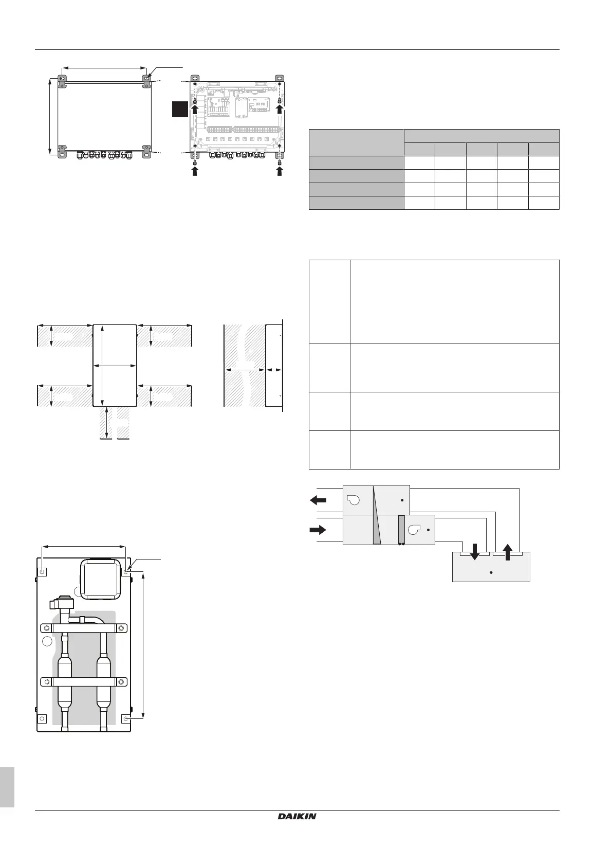
324
360
4× Ø6
(mm)
4×
4 For electrical wiring: see "15.1.1To connect the electrical wiring
to the control box"[425].
5 Close and lock the cover after installation to ensure that the
control box is watertight.
13.2 Expansion valve kit
13.2.1 Installation site requirements of the
expansion valve kit
Mind the following spacing installation guidelines:
≥250≥250
≥100≥100
(mm)
≥100≥150
≥600≥600
≥250≥250
≥100≥100
≥250≥250
≥100
≥100
≥250≥250
≥100
≥100
4980.5
215
401
13.2.2 To install the expansion valve kit
1 Make sure that the expansion valve kit is installed vertically.
2 Remove the cover by unscrewing 4× M5.
3 Drill 4 holes on the correct position (measurements as indicated
in figure below) and fix the expansion valve kit securely with 4
screws through the provided holes Ø9mm.
340
(mm)
192.5
4× Ø9
13.3 Thermistors
13.3.1 Location of the thermistors
Different thermistors need to be installed depending on the control
type. Follow the table below for this.
Thermistor Control type
X Y W Z Z'
R1T: Suction air — — — ● ●
R2T: Liquid pipe ● ● ● ● ●
R3T: Gas pipe ● ● ● ● ●
R4T: Discharge air — — — — ●
● Required
— Not required
Correct installation of the thermistors is required to ensure good
operation.
R1T Thermistor (suction air)
Install the thermistor either in the room that needs
temperature control or in the suction area of the air
handling unit.
Note: For room temperature control the delivered
thermistor (R1T) can be replaced by an optional remote
sensor kit (see the technical engineering data).
R2T Thermistor (liquid pipe)
Install the thermistor behind the distributor on the
coldest pass of the heat exchanger (contact your heat
exchanger dealer).
R3T Thermistor (gas pipe)
Install the thermistor at the gas pipe of the heat
exchanger as close as possible to the heat exchanger.
R4T Thermistor (discharge air)
Install the thermistor in the discharge area of the air
handling unit.
AHU
R1T*
R1T**
R4T
R2T R3T
b
a
f
e
c d
AHU Air handling unit
*/** Location of R1T can be chosen.
a Outdoor air
b Exhaust air
c Supply air
d Extract air
e Heat exchanger
f Heat recovery
Evaluation must be done to check if the air handling unit is protected
against freeze-up. This must be done during test operation.
The thermistor needs to be installed in an enclosed area. Install it
inside the air handling unit, or shield it to prevent it from getting
touched.
Bekijk gratis de handleiding van Daikin EKEXVA350, stel vragen en lees de antwoorden op veelvoorkomende problemen, of gebruik onze assistent om sneller informatie in de handleiding te vinden of uitleg te krijgen over specifieke functies.
Productinformatie
| Merk | Daikin |
| Model | EKEXVA350 |
| Categorie | Niet gecategoriseerd |
| Taal | Nederlands |
| Grootte | 5939 MB |


