Curtis 1226BL handleiding
Handleiding
Je bekijkt pagina 47 van 124
3 — PROGRAMMABLE PARAMETERS
pg. 39
Return to TOC Curtis Model 1226BL – July 2024
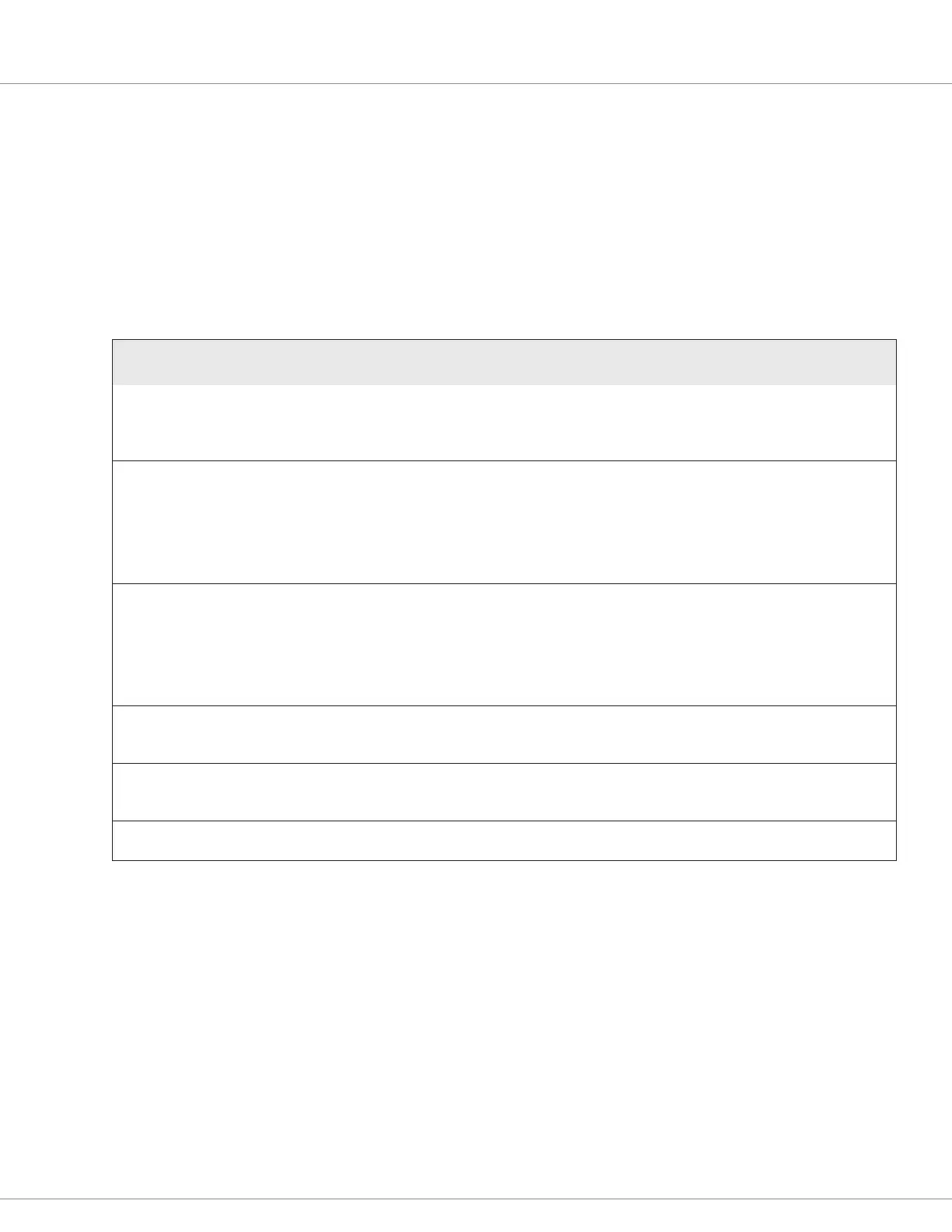
MAIN RELAY MENU
e Main Relay parameters apply to the main contactor in models that use a main contactor. For
other models, the parameters apply to the internal relay.
Note: e menu name depends upon whether the controller is an internal relay or main contactor model.
e following table describe the Main Relay parameters.
MAIN RELAY MENU
PARAMETER
CAN INDEX
VALUES
DEFAULT
RAW VALUES
DATA SIZE DESCRIPTION
Main Enable (1226BL-61XX
models only)
[PCF]
0x34C501
Off/On
On
0–1
16-bit
Species whether the main contactor is controlled by the
controller or by other controllers:
On = Controlled by the controller
Off = Controlled by other controllers
Pull In Voltage
0x34C801
0%–100%
100%
0–8192
16-bit
Species the initial voltage of the relay or contactor when the
driver is rst turned on.
The controller allows a high initial voltage to ensure the relay or
contactor closes. After 1 second, the voltage decreases to the
specied Holding Voltage.
If the Pull In Voltage value is too low to engage the relay or
contactor, a Main Contactor Did Not Close fault will occur.
Holding Voltage
0x34C601
0%–100%
80%
0–8192
16-bit
Species the voltage the controller applies to the relay or
contactor coil after the relay or contactor closes.
Set the Holding Voltage high enough so that the relay or
contactor remains closed under all shock and vibration
conditions that the vehicle is expected to encounter.
Note: Use the Main Relay/Contactor Driver PWM variable to
monitor the pull-in and holding voltages.
Open Delay
0x34CA01
0.0–40.0s
0.0s
0–10000
16-bit
Species how long the main relay or contactor should remain
closed when the interlock switch is opened.
Note: A delay prevents unnecessary cycling of the relay or contactor.
DNC Voltage Threshold
0x523300
0.00–10.00V
5.00V
0–1000
16-bit
Species the voltage threshold that the controller uses to check
whether the Main Contactor Did Not Close fault should be issued.
If 0 is specied, the fault check is disabled.
Main Welded PWM
0x34DB01
8–20%
10%
655–1638
16-bit
Species the PWM duty cycle that the controller uses to check
whether the Main Contactor Welded fault should be issued.
Bekijk gratis de handleiding van Curtis 1226BL, stel vragen en lees de antwoorden op veelvoorkomende problemen, of gebruik onze assistent om sneller informatie in de handleiding te vinden of uitleg te krijgen over specifieke functies.
Productinformatie
| Merk | Curtis |
| Model | 1226BL |
| Categorie | Niet gecategoriseerd |
| Taal | Nederlands |
| Grootte | 15971 MB |


