Curtis 1220E handleiding
Handleiding
Je bekijkt pagina 21 van 72
3 — PROGRAMMABLE PARAMETERS
pg. 17
Return to TOC Curtis Model 1220E – August 2022
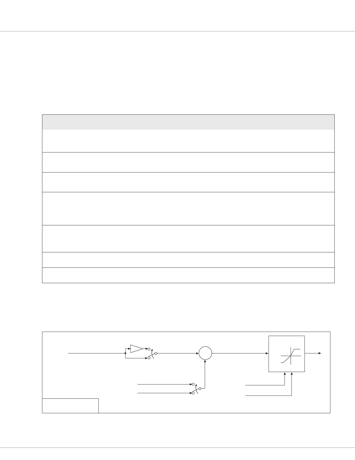
is less than Command Analog Right then the three points of the map are dened (in order from
le to right in the diagram above) as:
X = Command Analog Le and Y = –100%
X = Command Analog Center and Y = 0%
X = Command Analog Right and Y = 100%
1 - CAN COMMAND
NAME
ALLOWABLE
RANGE RAW DATA DESCRIPTION
CAN Steer Device Type
(0x336B00, 8bits)
0 – 1
0 – 1
Sets the CAN command data transform type:
0 = Both CAN1 and CAN2 commands to the primary
1 = CAN1 command to the primary and CAN2 command to the supervisor.
CAN Steer Center Offset
(0x336500, 16bits)
–32768 – 32767
–32768 – 32767
Denes the position (in counts) required to produce a steer command of
center position (Steer Command = 0%). This allows a service technician to
recalibrate center without having to physically adjust the sensor.
CAN2 Steer Center Offset
(0x336600, 16bits)
–32768 – 32767
–32768 – 32767
Denes the position (in counts) required to produce a steer command2 of
center position (Steer Command2 = 0%). This allows a service technician
to recalibrate center without having to physically adjust the sensor.
CAN Steer Left Stop to Center
(0x336700, 16bits)
–32768 – 0
–32768 – 0
Denes the total CAN steer command sensor counts to produce a steer
command from the center position (Steer Command = 0%) to the full left
position
(Steer Command = –100%). Left Stop to Center is always a negative
number.
CAN Steer Right Stop to Center
(0x336800, 16bits)
0 – 32767
0 – 32767
Denes the total CAN steer command sensor counts to produce a steer
command from the center position (Steer Command = 0%) to the full
right position (Steer Command = 100%). Right Stop to Center is always a
positive number.
CAN Steer Swap Direction
(0x336900, 8bits)
OFF / ON
0 / 1
Changes the direction (left or right) of the CAN steer command input.
CAN2 Steer Swap Direction
(0x336A00, 8bits)
OFF / ON
0 / 1
Changes the direction (left or right) of the CAN2 steer command input.
When setting up a steering command CAN device, for the system to be EN 13849 compliant, one
PDO must be sent to the main processor and one to the supervisor. For additional security, it is
recommended that the PDO sent to the supervisor be the opposite polarity and that Swap Direction
be set for the supervisor only. Contact Curtis technical support for help with setting up PDOs.
Figure 5
Command input device CAN
+
−
CAN Steer Command
-1
CAN Steer Counts
Swap Direction
Center Offset
CAN Relative Center Offset
Absolute Mode
Right Stop to Center
Left Stop to Center
Normalization
+100%
0
0
−100%
−32768
+32767
Programmable Parameter
Monitor Item
Bekijk gratis de handleiding van Curtis 1220E, stel vragen en lees de antwoorden op veelvoorkomende problemen, of gebruik onze assistent om sneller informatie in de handleiding te vinden of uitleg te krijgen over specifieke functies.
Productinformatie
| Merk | Curtis |
| Model | 1220E |
| Categorie | Niet gecategoriseerd |
| Taal | Nederlands |
| Grootte | 9449 MB |


