Crestron Green Light GLXX-2DIM8 handleiding
Handleiding
Je bekijkt pagina 12 van 24
Dimming Panel Crestron Green Light Express™
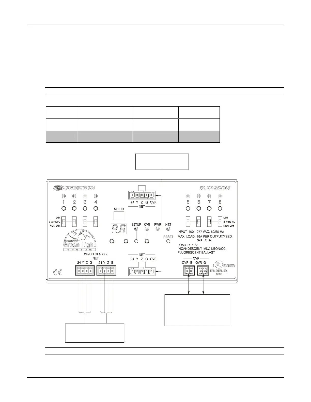
Control Wiring (Section B)
The bottom of the cabinet contains Cresnet
®
connections for interfacing to the rest of the Crestron
®
control system.
It also provides overrides input which can be tied to devices such as the GLS-PLS-120/277 phase-loss sensor, or
other devices that provide a dry contact closure (manual switch, fire alarm relay, etc.).
To ensure optimum performance over the full range of your installation topology, use Crestron certified wire.
Failure to do so may incur additional charges if support is required to identify performance deficiencies because of
using improper wire.
NOTE: Interface connectors for NET (x4), and OVERRIDE (x3) ports are provided.
Wire Gauge and Torque Values
TERMINAL CONNECTOR MAX
WIRE RANGE
TORQUE STRIP
LENGTH
NET 26-12 AWG
4.43 lb-in
(0.5 Nm)
1/4”
(6 mm)
OVERRIDE 26-12 AWG
4.43 lb-in
(0.5 Nm)
1/4”
(6 mm)
Connector Wiring
NET:
TO CONTROL SYSTEM AND
OTHER CRESNET DEVICES
OVERRIDE:
FROM GLS-PLS-120/277, FROM
OTHER CABINET,
FROM ALARM, ETC.
(OPTIONAL); TO OTHER
CABINET(S) IF NECESSARY
RED
WHITE
BLUE
BLACK
RED
WHITE
BLUE
BLACK
MODULES:
TO GLXX-2DIM8
MODULES (PREWIRED)
NOTE: For instructions on network wiring, refer to “Appendix C: Network Wiring” on page 21.
12 • Crestron Green Light Express™ Dimming Panel Installation Guide – DOC. 6889B
Bekijk gratis de handleiding van Crestron Green Light GLXX-2DIM8, stel vragen en lees de antwoorden op veelvoorkomende problemen, of gebruik onze assistent om sneller informatie in de handleiding te vinden of uitleg te krijgen over specifieke functies.
Productinformatie
| Merk | Crestron |
| Model | Green Light GLXX-2DIM8 |
| Categorie | Niet gecategoriseerd |
| Taal | Nederlands |
| Grootte | 3430 MB |


