Carrier WeatherMaker 48GE handleiding
Handleiding
Je bekijkt pagina 35 van 80
35
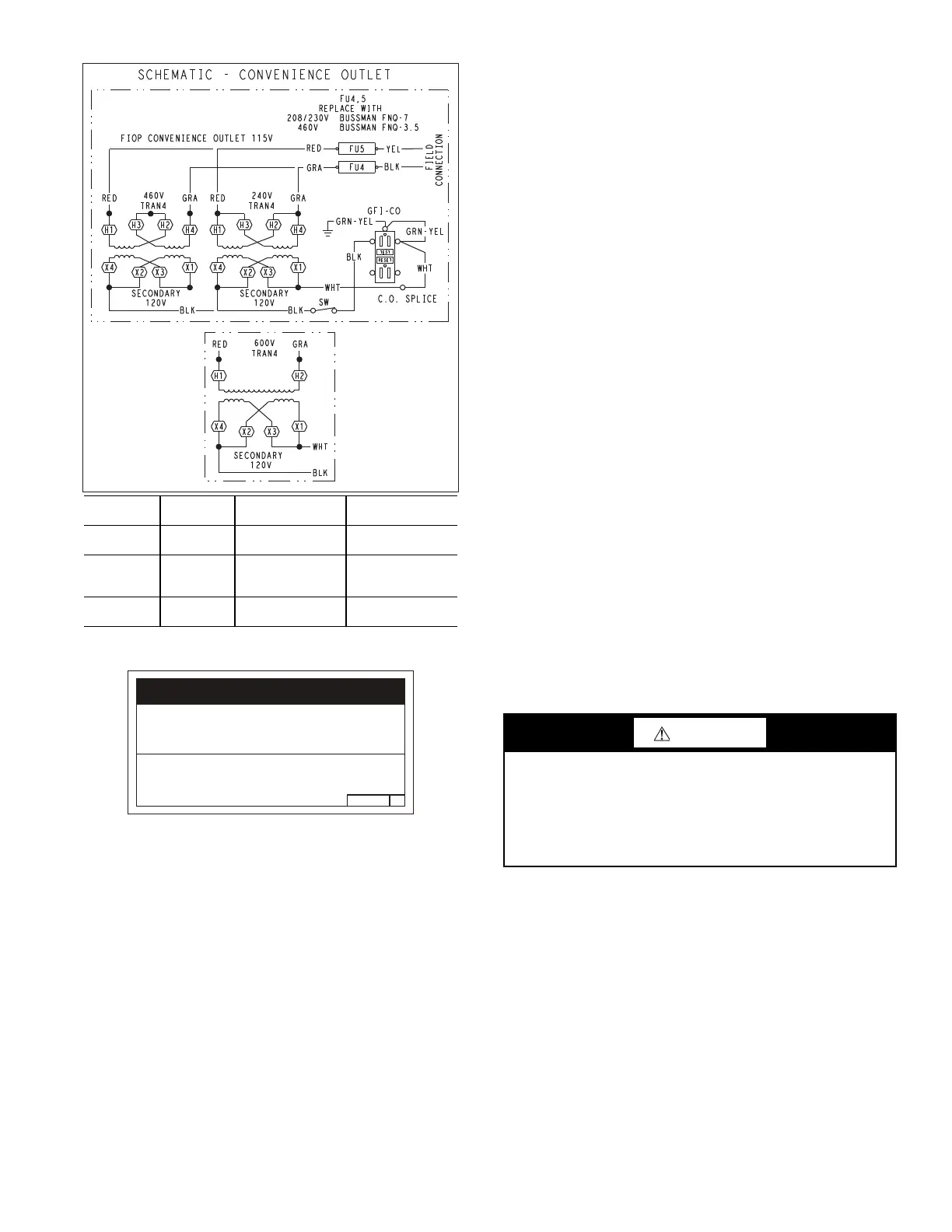
Fig. 51 — Powered Convenience Outlet Wiring
Fig. 52 — Convenience Utilization Notice
The electrical entrance is located in the control box area and can
be accessed through the control box access panel. An embossed
area is provided with 3 knock outs. High voltage is brought
through the multi knock out by removing the appropriate size for
the size of the fitting required. A 7/8 in. knock out is provided for
low voltage. An additional 7/8 in. knock out is provided for a
115 volt line which is used when the unit is equipped with the non-
unit powered convenience outlet option.
All required fittings are field supplied. Install fittings when access
to both top and bottom of the base pan is available. See electrical
and gas connections for routing and connection information.
UNITS WITHOUT THRU-BASE CONNECTIONS
1. Install liquid tight conduit between disconnect and control
box.
2. Pull correctly rated high voltage wires through the conduit.
3. Install power lines to terminal connections as shown in
Fig. 48.
FIELD CONTROL WIRING
The 48GE unit requires an external temperature control device.
This device can be a thermostat (field-supplied) or a SystemVu™
controller (available as factory-installed option for use on a Carrier
Comfort Network
®
or as a stand-alone control).
All low-voltage wiring should be routed through the provided
wire ties (see Fig. 54) down the left side of the control box or se-
cured to the unit control box with an electrical conduit in order to
provide UL-required clearance between high-voltage and low
voltage wiring.
THERMOSTAT
Install a Carrier-approved accessory 2-stage thermostat according
to installation instructions included with the accessory. Locate the
thermostat accessory on a solid wall in the conditioned space to
sense average temperature in accordance with the thermostat in-
stallation instructions.
If the thermostat contains a logic circuit requiring 24 v power, use
a thermostat cable or equivalent single leads of different colors
with minimum of 7 leads. If the thermostat does not require a 24 v
source (no “C” connection required), use a thermostat cable or
equivalent with minimum of 6 leads. Check the thermostat instal-
lation instructions for additional features which might require ad-
ditional conductors in the cable.
For wire runs up to 50 ft (15 m), use no. 18 AWG (American Wire
Gauge) insulated wire (35°C minimum). For 50 to 75 ft (15 to
23 m), use no. 16 AWG insulated wire (35°C minimum). For over
75 ft (23 m), use no. 14 AWG insulated wire (35°C minimum).
All wire sizes larger than no. 18 AWG cannot be directly connect-
ed to the thermostat and will require a junction box and splice at
the thermostat.
UNITS WITHOUT THRU-BASE CONNECTIONS
Correctly rated low voltage wire can be routed through the rubber
grommet located on the corner post adjacent to the control box ac-
cess panel. Route wire through the grommet and then route the
wire behind the corner post utilizing the factory provided wire ties
secured to the control box. This will ensure separation of the field
low voltage wire and the high voltage circuit. Route the low volt-
age wire to the unit control board. See Fig. 53 and 54.
NOTE: If utilizing the thru-the-base connections, route the low
voltage wire through the wire ties to the unit control board.
HEAT ANTICIPATOR SETTINGS
Set heat anticipator settings at 0.14 amp for the first stage and
0.14 amp for second-stage heating.
TRANSFORMER CONNECTION FOR 208 V POWER
SUPPLY
All units except 208/230 v units are factory wired for the voltage
shown on the nameplate. If the 208/230 v unit is to be connected to
a 208 v power supply, the control transformer must be rewired by
moving the black wire with the 1/4 in. female spade connector
from the 230 v connection and moving it to the 208 v 1/4 in. male
terminal on the primary side of the transformer. Refer to unit label
diagram for additional information.
UNIT
VOLTAGE
CONNECT
AS
PRIMARY
CONNECTIONS
TRANSFORMER
TERMINALS
208,230 240
L1: RED +YEL
L2: BLU + GRA
H1 + H3
H2 + H4
460 480
L1: RED
Splice BLU + YEL
L2: GRA
H1
H2 + H3
H4
575 600
L1: RED
L2: GRA
H1
H2
2.050HE501288
NOTICE/AVIS
Convenience Outlet Utilization
Maximum Intermittent Use 15 - Amps
Maximum Continuous Use 8 - Amps
Observe a 50% limit on the circuit
Loading above 8 - Amps
Utilisation de la prise utilitaire
Usage intermittent maximum 15 - Amps
Usage continu maximum 8 - Amps
Observez une limite de 50% sur le circuit
Chargement au-dessus de 8 - Amps
CAUTION
UNIT DAMAGE HAZARD
Failure to follow this caution may cause a short circuit.
Carefully check the connection of control conductor for indoor
fan control at terminal G. Connecting the indoor fan lead to ter-
minal C will cause a short circuit condition, which can cause
component damage inside the unit or at the thermostat.
Bekijk gratis de handleiding van Carrier WeatherMaker 48GE, stel vragen en lees de antwoorden op veelvoorkomende problemen, of gebruik onze assistent om sneller informatie in de handleiding te vinden of uitleg te krijgen over specifieke functies.
Productinformatie
| Merk | Carrier |
| Model | WeatherMaker 48GE |
| Categorie | Niet gecategoriseerd |
| Taal | Nederlands |
| Grootte | 10499 MB |


