Carrier WeatherMaker 48GE handleiding
Handleiding
Je bekijkt pagina 28 van 80
28
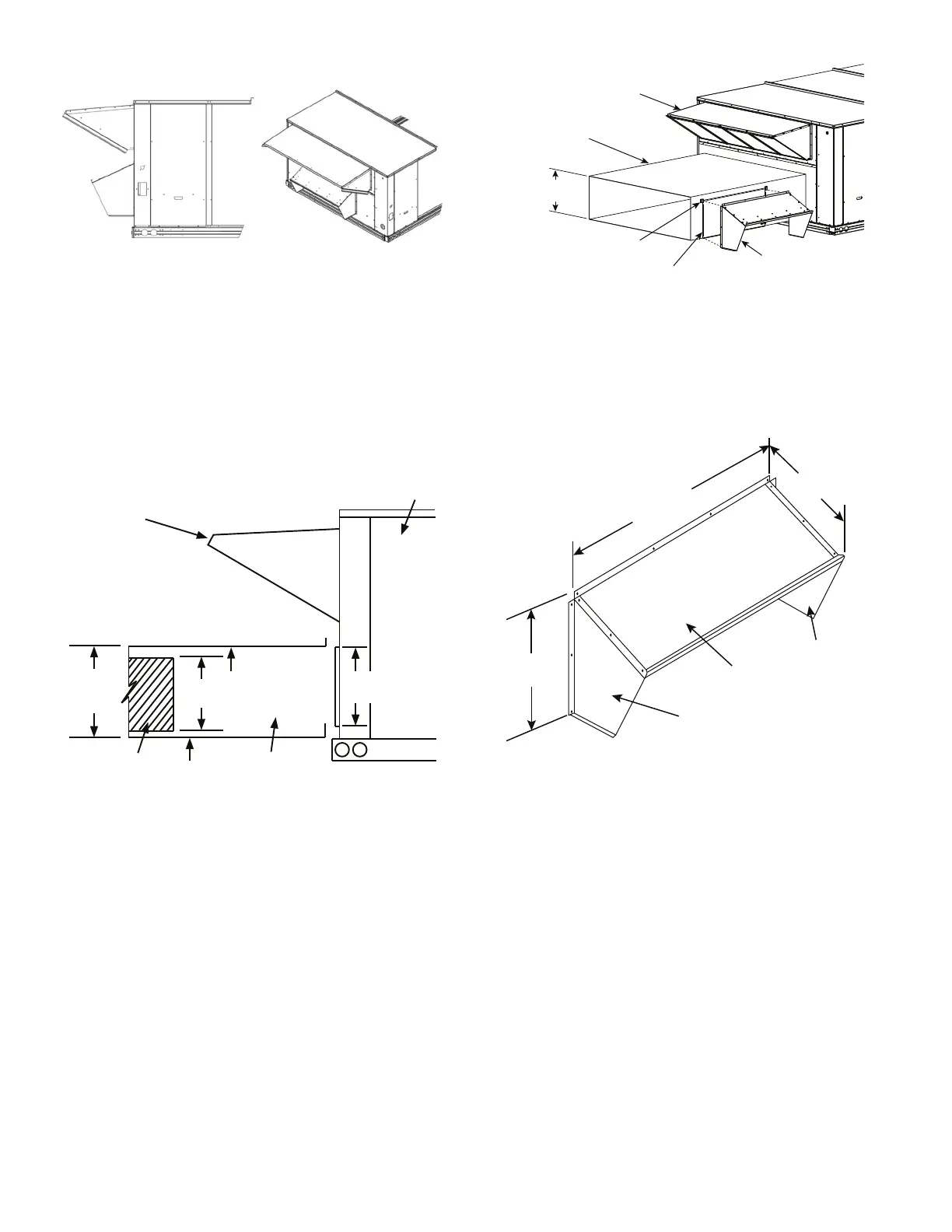
Figure 33 illustrates the installed barometric hood parts.
Fig. 33 — Installed Barometric Hood Side View and
Isometric View
BAROMETRIC HOOD (HORIZONTAL CONFIGURATION)
For horizontal return and field installed economizer, install the
economizer as follows:
1. Install the field provided horizontal ductwork onto the unit.
Duct height must be at least 19-1/2 in. (495 mm) high, how-
ever the duct can be no taller than the top of the relief opening
in the bottom panel, or airflow into the outside air hood will
be restricted. See Fig. 34.
2. Cut a 16 in. x 36 in. (406 mm x 914 mm) opening in the
return duct for the relief damper (see Fig. 34).
Fig. 34 — Relief Damper
3. On the field installed economizer (CRECOMZR0**A00), a
birdscreen or hardware cloth is shipped attached to the
bottom panel used for vertical applications.
NOTE: This panel is not used for horizontal return applications.
Remove the screen from the provided panel and install it over the
relief opening cut in return duct.
4. Using the blade brackets, install the relief damper onto the
side of the return duct (see Fig. 35). The two brackets and
relief damper are provided with the economizer.
Fig. 35 — Installing CRBARHOD001A00 Over Relief
Damper
5. Using the provided hardware, screw the
CRBARHOD001A00 hood sides and top together (see
Fig. 36).
NOTE: CRBARHOD001A00 is a separate accessory that
must be ordered with the unit and ships in a separate box.
Fig. 36 — CRBARHOD001A00 Hood Sides and Top
Caulk the backside of the mating flanges to ensure a watertight
seal. Install the CRBARHOD001A00 over the relief damper and
screw to the return duct, as illustrated in Fig. 35.
Step 10 — Install Flue Hood and Combustion Air
Hood
The flue hood is shipped screwed to the fan deck inside the burner
compartment. Remove the burner access panel and then remove
the flue hood from its shipping location. Using the screws provid-
ed, install flue hood and screen in location shown in Fig. 37.
The combustion air hood is attached to the back of the burner ac-
cess panel. Remove the 2 screws securing the hood to the back of
the burner access panel. Using the 2 screws, re-attach the hood to
the front of the burner access panel as shown in Fig. 18.
Unit
Outside
Air Hood
Min.
19-1/2"
[495 mm]
Relief
Opening
Return
Duct
16"
[406 mm]
1"
[25 mm]
18-3/8"
[467 mm]
Outdoor
Air Hood
*Relief
Damper
CRBARHOD001A00
Relief Hood
(ordered separately)
*Provided with
Economizer
Field Supplied
Return Duct
*Blade
Bracket
Min 19-1/2˝
[495 mm]
40-1/2"
[1029 mm]
15"
[381 mm]
19-1/2"
[495 mm]
Hood
Top
Left
Hood Side
Right
Hood Side
Bekijk gratis de handleiding van Carrier WeatherMaker 48GE, stel vragen en lees de antwoorden op veelvoorkomende problemen, of gebruik onze assistent om sneller informatie in de handleiding te vinden of uitleg te krijgen over specifieke functies.
Productinformatie
| Merk | Carrier |
| Model | WeatherMaker 48GE |
| Categorie | Niet gecategoriseerd |
| Taal | Nederlands |
| Grootte | 10499 MB |


