Carrier WeatherMaker 48GE handleiding
Handleiding
Je bekijkt pagina 21 van 80
21
Step 4 — Provide Unit Support
ROOF CURB MOUNT
Accessory roof curb details and dimensions are shown in
Fig. 19-21. Assemble and install accessory roof curb in accor-
dance with instructions shipped with the curb.
NOTE: The gasketing of the unit to the roof curb is critical for a
watertight seal. Install gasket supplied with the roof curb as shown
in Fig. 19-21. Improperly applied gasket can also result in air leaks
and poor unit performance.
Curb should be level. This is necessary for unit drain to function
properly. Unit leveling tolerances are shown in Fig. 17. Refer to
Accessory Roof Curb Installation Instructions for additional infor-
mation as required.
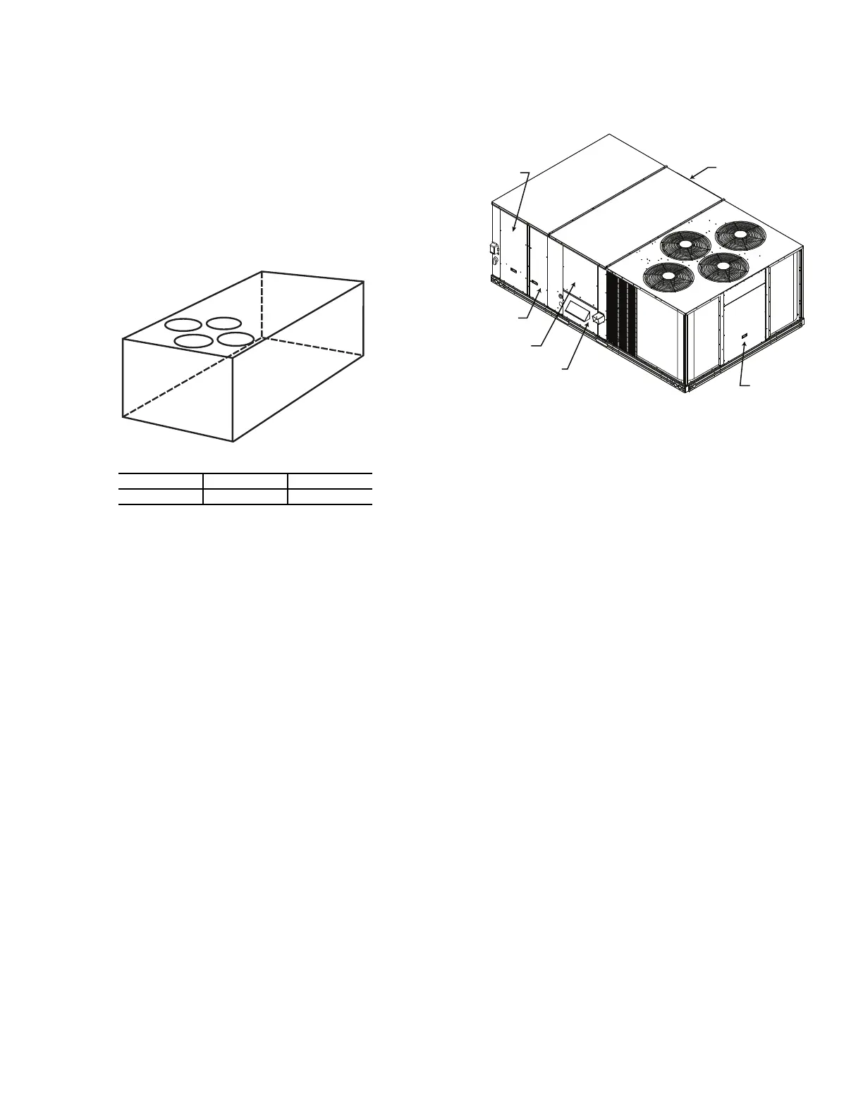
Fig. 17 — Unit Leveling Tolerances
Install insulation, cant strips, roofing felt, and counter flashing as
shown. Ductwork must be attached to curb and not to the unit.
Thru-the-base power connection must be installed before the unit
is set on the roof curb. If field-installed thru-the-roof curb gas con-
nections are desired remove knockout in basepan located in the
gas section, see Fig. 18 for location. Gas connections and power
connections to the unit must be field installed after the unit is in-
stalled on the roof curb.
If electrical and control wiring is to be routed through the basepan,
remove the knockouts in the basepan located in the control box ac-
cess area (see Fig. 18). For basepan knockout locations for vertical
airflow units see Fig. 2, 7, or 12; for horizontal airflow units see
Fig. 3, 8, or 13.
Fig. 18 — Typical Access Panel and Compressor
Locations
SLAB MOUNT (HORIZONTAL UNITS ONLY)
Provide a level concrete slab that extends a minimum of 6 in.
(150 mm) beyond unit cabinet. Install a gravel apron in front of
condenser coil air inlet to prevent grass and foliage from obstruct-
ing airflow.
NOTE: Horizontal units may be installed on a roof curb if
required.
ALTERNATE UNIT SUPPORT (IN LIEU OF CURB OR
SLAB MOUNT)
A non-combustible sleeper rail can be used in the unit curb sup-
port area. If sleeper rails cannot be used, support the long sides of
the unit with a minimum of 3 equally spaced 4 in. x 4 in. (102 mm
x 102 mm) pads on each side. Locate pads so that they support the
rails. Make sure to avoid the fork openings.
MAXIMUM ALLOWABLE DIFFERENCE in. (mm)
A-B B-C A-C
0.25 (6) 0.5 (12) 0.5 (12)
A
B
C
Hood Carton Location
(rear access panel)
Control Box
Access Panel
Filter and
Indoor Coil
Access Panel
Indoor Blower
Access Panel
Gas Heat
Access Panel
Compressor
Access Panel
Bekijk gratis de handleiding van Carrier WeatherMaker 48GE, stel vragen en lees de antwoorden op veelvoorkomende problemen, of gebruik onze assistent om sneller informatie in de handleiding te vinden of uitleg te krijgen over specifieke functies.
Productinformatie
| Merk | Carrier |
| Model | WeatherMaker 48GE |
| Categorie | Niet gecategoriseerd |
| Taal | Nederlands |
| Grootte | 10499 MB |


