Carrier 39S handleiding
Handleiding
Je bekijkt pagina 60 van 64
60
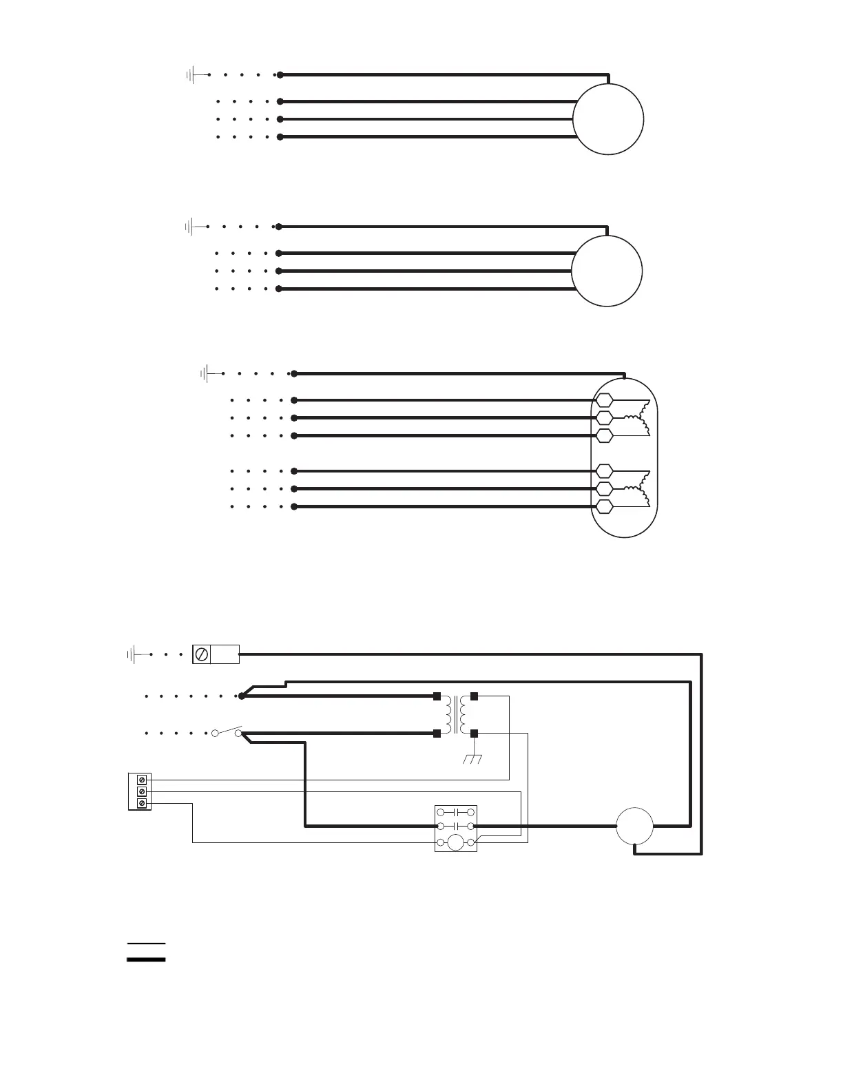
Fig. 77 — Typical Wiring Diagrams, Dual Speed Fan Motors
Fig. 78 — Typical Wiring Diagram, Single-Phase Relay Control
N
GRN/
100
L1 (HIG
H)
L1 (LOW
)
BLK/102
RED/103
WHT/101
BLK/102
RED/103
WHT/101
GRN/100
L2 (COM)
GRN/
100
L1 (HIG
H)
L1 (LOW
)
BLK/102
RED/103
YEL/101
BLK/102
RED/103
YEL/101
GRN/100
1
2
3
LOW
SPEED
11
12
13
HIGH
S
PEED
L1
GRN/
100
L2
L3
BLU/102
YEL/103
BLK/101
RED/104
ORN/105
BRN/106
BLU/102
YEL/103
BLK/101
RED/104
ORN/105
BRN/106
LOW
SPEED
HIGH
SPEED
L1
L2
L3
GRN/100
115 V OR 265 V, SINGLE PHASE
208-230 V, SINGLE PHASE
208-230 V, 460 V, THREE PHASE
SEE MOTOR
NAMEPLATE
FOR WIRING
DETAIL
SEE MOTOR
NAMEPLATE
FOR WIRING
DETAIL
A39-4494
NOTES:
1. Field-supplied fan controls must prevent simultaneous engagement of both high and low speeds.
2. Field-supplied fan controls must provide motor overload protection and both motor windings must be connected
in the correct phase sequence.
BA FR
47
69
R
C
G
L1
N
BLK/141
USE COPPER
SUPPLY WIRES.
GND
WHT/140
TRAN
1
24V
GRN
57
0
RED/500
BRN/50
1
BRN/501
RED/500
BRN/505
BLK/502
BLK/50
2
WHT/131
WHT/14
0
BLK/13
4
BLK/134 BLK/141
FAN
MOTO
R
BRN/50
5
TB
1
BLK/133
WHT/131
BLK/133
DISC
1
GRN/142
GRN/
142
REFER TO MOTOR
NAMEPLATE FOR
WIRING DETAILS.
A39-4495
LEGEND
DISC1 — Disconnect
FR — Fan Relay
GND — Ground
TRAN1 — Transformer
High Voltage Wiring
Low Voltage Wiring
Bekijk gratis de handleiding van Carrier 39S, stel vragen en lees de antwoorden op veelvoorkomende problemen, of gebruik onze assistent om sneller informatie in de handleiding te vinden of uitleg te krijgen over specifieke functies.
Productinformatie
| Merk | Carrier |
| Model | 39S |
| Categorie | Niet gecategoriseerd |
| Taal | Nederlands |
| Grootte | 10967 MB |


