Carrier 39L handleiding
Handleiding
Je bekijkt pagina 57 van 76
57
Fig. 62 — Fan Discharge Positions, Sizes 21 and 25
START-UP
Check List
Make a walkway inside unit components to protect insulation. Re-
move all construction debris from unit interior. Remove walkway
before starting unit.
FILTERS
Install unit filters in all filter sections.
FANS
1. Check lubrication of fan, motor bearings, and linkages.
a. Note that bearings are shipped completely full of grease
for corrosion protection and may run warm temporarily
on start-up until excess grease has discharged.
b. Hand-operate all linkages, such as damper and guide
vanes, to check for freedom of movement.
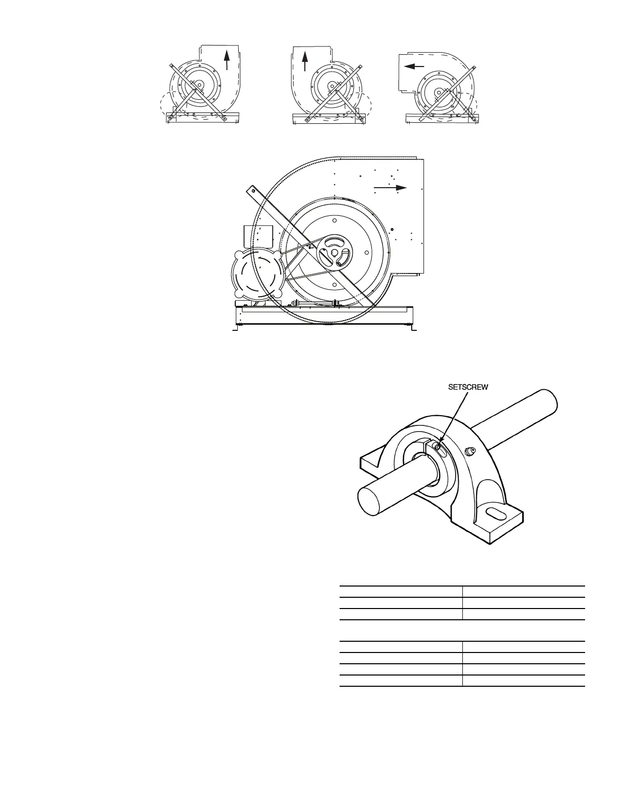
2. Check tightness of bearing setscrews or locking collars
(Fig.
63). Also, check tightness of setscrews on fan wheels
and sheaves.
3. Check tightness of fan shaft bearing mounting.
4. Recheck sheave alignment and belt tension. (Refer to Fig. 40
and 41.)
5. Hand turn fan to make certain fan wheel does not rub in
housing.
6. Check fan speed with a strobe-type tachometer or use the fol-
lowing formula: Obtain the motor rpm from the fan motor
nameplate and read sheave pitch diameters marked on the fan
and motor pulleys, or estimate the pitch diameters by using
the pulley outside diameters.
Fig. 63 — Fan Shaft Bearing Details
UBF
UBR
THR
THF
LEGEND
THF — Top Horizontal Front
THR — Top Horizontal Rear
UBF — Upblast Front
UBR — Upblast Rear
SQUEEZE-TYPE LOCKING COLLAR
BEARING SETSCREW TORQUE (in.-lb)
BEARING HOLDDOWN BOLT TORQUE (ft-lb)
39L UNIT SIZE TORQUE
03,06,08,10,12 70
15,18,21,25 90
BOLT SIZE TORQUE
3/8-16 30
1/2-13 63
5/8-11 100
Bekijk gratis de handleiding van Carrier 39L, stel vragen en lees de antwoorden op veelvoorkomende problemen, of gebruik onze assistent om sneller informatie in de handleiding te vinden of uitleg te krijgen over specifieke functies.
Productinformatie
| Merk | Carrier |
| Model | 39L |
| Categorie | Niet gecategoriseerd |
| Taal | Nederlands |
| Grootte | 14640 MB |


