Carrier 39L handleiding
Handleiding
Je bekijkt pagina 36 van 76
36
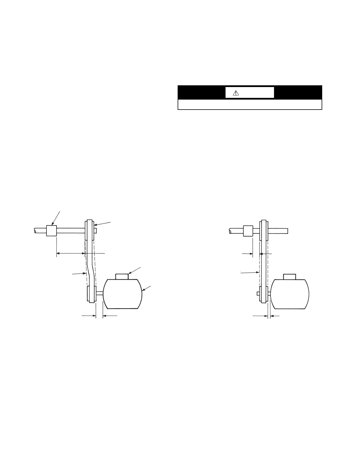
Install Sheaves on Motor and Fan Shafts
Factory-supplied drives are pre-aligned and tensioned, however,
Carrier recommends that you check the belt tension and alignment
before starting the unit. Always check the drive alignment after
adjusting belt tension.
When field installing or replacing sheaves, install sheaves on fan
shaft and motor shaft for minimum overhang. (See Fig.
40.) Use
care when mounting sheave on fan shaft; too much force may
damage bearing. Remove rust-preventative coating or oil from
shaft. Make sure shaft is clean and free of burrs. Add grease or lu
-
bricant to bore of sheave before installing.
The 39L fan, shaft, and drive pulley are balanced as a complete as-
sembly to a high degree of accuracy. If excessive unit vibration is
present after fan pulley replacement, the unit must be rebalanced.
For drive ratio changes, always reselect the motor pulley — do not
change the fan pulley.
ALIGNMENT
Make sure that fan shafts and motor shafts are parallel and level.
The most common causes of mis-alignment are nonparallel shafts
and improperly located sheaves. Where shafts are not parallel,
belts on one side are drawn tighter and pull more than their share
of the load. As a result, these belts wear out faster, requiring the
entire set to be replaced before it has given maximum service. If
misalignment is in the sheave, belts will enter and leave the
grooves at an angle, causing excessive belt cover and sheave wear.
1. Shaft alignment can be checked by measuring the distance
between the shafts at 3 or more locations. If the distances are
equal, then the shafts will be parallel.
2. Sheave alignment:
Fixed sheaves
To check the location of the fixed sheaves on the shafts, a straight-
edge or a piece of string can be used. If the sheaves are properly
lined up the string will touch them at the points indicated by the
arrows in Fig.
41.
Adjustable sheave
To check the location of adjustable sheave on shaft, make sure that
the centerlines of both sheaves are in line and parallel with the
bearing support channel. See Fig.
41. Adjustable pitch drives are
installed on the motor shaft.
3. Rotating each sheave a half revolution will determine
whether the sheave is wobbly or the drive shaft is bent. Cor
-
rect any misalignment.
4. With sheaves aligned, tighten cap screws evenly and
progressively.
NOTE: There should be a 1/8-in. to 1/4-in. gap between the mat-
ing part hub and the bushing flange. If gap is closed, the bushing is
probably the wrong size.
Fig. 40 — Determining Sheave-Shaft Overhang
CAUTION
With adjustable sheave, do not exceed maximum fan rpm.
Shaft Bearing
Driven Sheave
Excessive
Overhang
Sheaves
Misaligned
Excessive
Overhang
Electrical
Junction Box
Motor and Drive Sheave
Minimum
Overhang
Aligned
Sheave
Minimum
Overhang
Poor Installation
Better Installation
Bekijk gratis de handleiding van Carrier 39L, stel vragen en lees de antwoorden op veelvoorkomende problemen, of gebruik onze assistent om sneller informatie in de handleiding te vinden of uitleg te krijgen over specifieke functies.
Productinformatie
| Merk | Carrier |
| Model | 39L |
| Categorie | Niet gecategoriseerd |
| Taal | Nederlands |
| Grootte | 14640 MB |


