Carel pCO5 handleiding
Handleiding
Je bekijkt pagina 9 van 48
9
ENG
pCO5plus +0300020EN rel. 1.9 - 28.03.2025
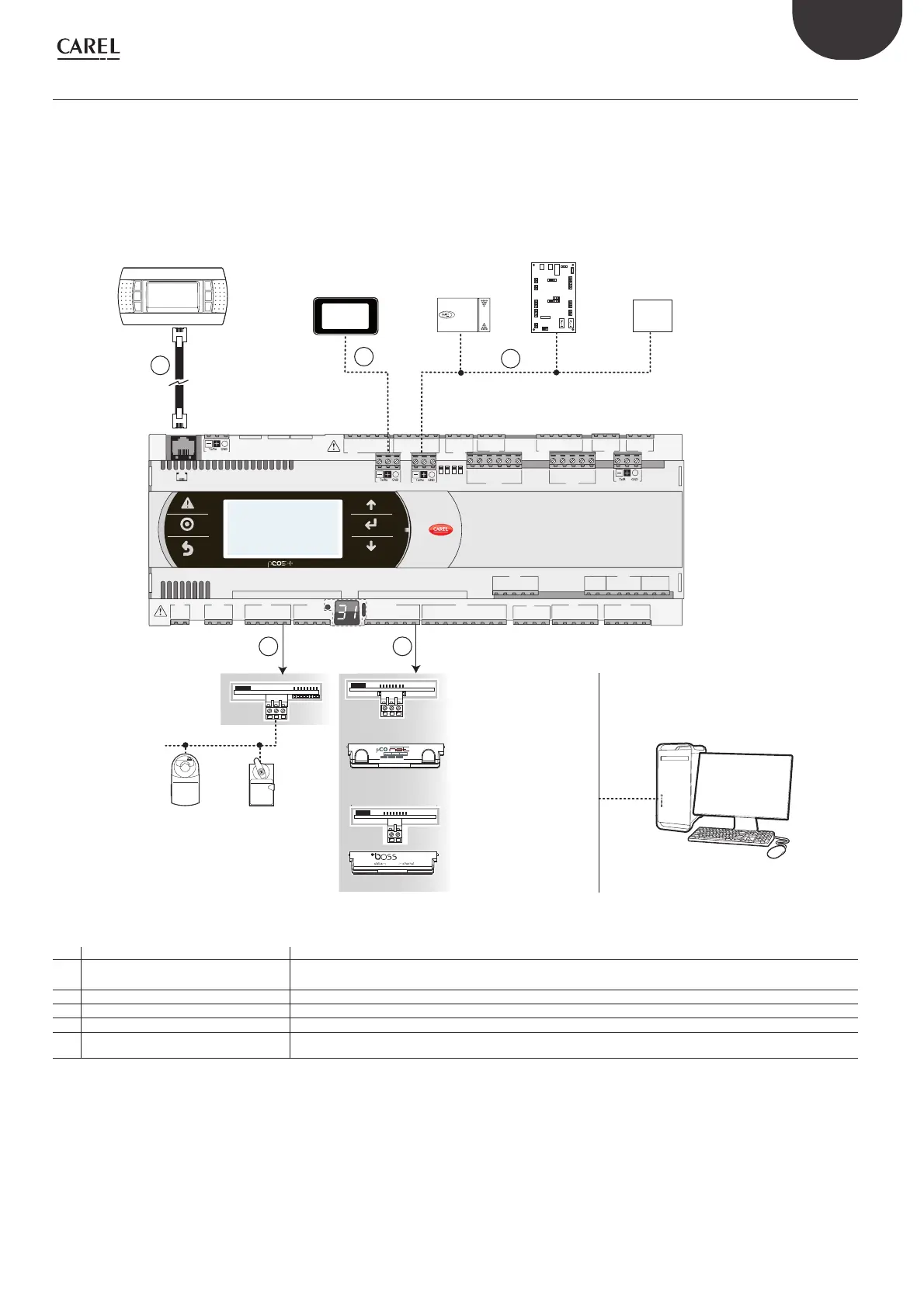
1.3 Functional layout
The gure below shows the functional layout of an air handling unit. Damper actuators and valve actuators are eld devices that communicate through
Fieldbus 1 (ref. C). Fieldbus 2 (ref. E) is the medium through which the serial probes communicate the values measured, and through which the humidi er
control board and the fans exchange data and receive setpoints from the controller. The built-in terminal and the remote terminal, which communicate via
pLAN (ref. A), are used for installing the application program and for commissioning the system. The pGDx touchscreen terminal, intuitive and simple to use,
can be used while the unit is normally working to set switch-on and switch-o times, to enter the main parameters, to perform other advanced functions
of the application program and to view any alarms triggered. In this case the data is communicated through the BMS2 serial port (ref. D). The system can be
connected to a supervision system (KNX®, LON®, BACnet™, etc.) after installing the relative BMS1 expansion card (ref. B).
BELIMO
Scheda seriale RS485
Scheda interfaccia
BACnet™ RS485
Servocontrollo
della serranda
BELIMO
Valvola di
servocontrollo
MP -BUS
Scheda MP-BUS
584SRsutats
GNX RS485
+ –
P1 P2 P3
B ACnet
™
MS/TP
FieldBus 1
BMS 1
J1
J24 J2 J3
J4
J5 J7
J8
J20
J21
J14
J10
J13J12
J22
J16 J1
7
J18
J15
J6
J19
FieldBus card
B M S card
J23 FBus2
J11 pLAN
J25 BMS2
J26 FBus2
43 2 1
Sonde seriali
pGDx
touch screen
Terminale
Scheda controllo
umidicatori
Dispositivo
terze parti
FAN
FieldBus 2
D
E
BMS2
A
pLAN
C
B
one
Scheda interfaccia
KNX®
Scheda interfaccia
Ethernet™
Fig. 1.c
Ref. Serial port/Connectors Connection to:
A pLAN/J10, J11
up to 3 terminals (semi-graphic terminals such as pGDs or touch screens such as pGDT / pGDx)
up to 32 devices in a pLAN network (pCO controllers, EVD Evolution valve drivers, terminals)
B BMS 1 Serial Card a building automation system, after installing the relative BMS card (see par. 1.4)
C FieldBus 1 Serial Card sensors, actuators, etc., on a Fieldbus, after installing the relative card (see par. 1.5)
D BMS 2 / J25* pGDx terminals, GPRS connection modules (built-in card)
E
Fieldbus 2/J26 (and J23 on Large and Extralar-
ge versions)
sensors, actuators, etc., on a Fieldbus (built-in card)
Tab. 1.a
(*) available on P+5... models; not available on P+3... models; see par. 8.3.
Terminal
PGD touchscreen
terminal
Serial probes
Humidi er
control board
Device
MP-BUS card
Servo-control
valve
Damper
servo-control
RS485 serial card
BACnetTM RS485
interface card
EthernetTM/BACnetTM
interface card
LonWorks interface
card*
Bekijk gratis de handleiding van Carel pCO5, stel vragen en lees de antwoorden op veelvoorkomende problemen, of gebruik onze assistent om sneller informatie in de handleiding te vinden of uitleg te krijgen over specifieke functies.
Productinformatie
| Merk | Carel |
| Model | pCO5 |
| Categorie | Niet gecategoriseerd |
| Taal | Nederlands |
| Grootte | 10234 MB |

