Handleiding
Je bekijkt pagina 8 van 20
en Installation instructions
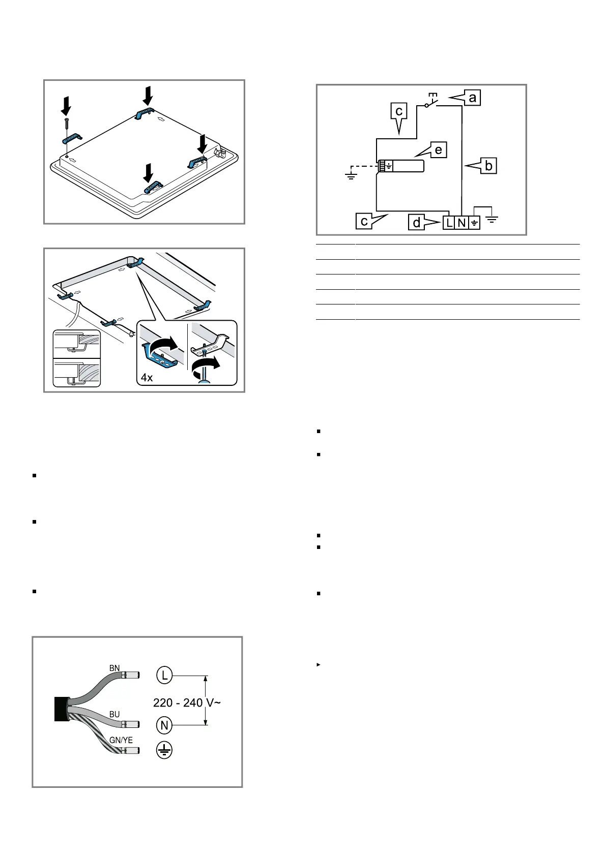
3.
Screw the brackets supplied into the specified posi-
tion so that they can turn freely.
4.
Turn the brackets and tighten them fully.
The position of the brackets depends on the worktop
thickness.
2.6 Electrical connection
Follow the instructions for electrical connection.
An electrical 10amp socket needs to be within 1m
of the hotplate to allow electrical connection. The
socket must remain accessible after installation of the
appliance.
This appliance is connected to the mains (240VAC)
by means of the connecting lead. The connecting
lead must be fixed to the kitchen unit to prevent it
from coming into contact with hot parts of the cook-
top or an oven installed underneath and remain ac-
cessible after installation of the cooktop.
This appliance must be earthed. When connecting the
cooktop ensure that the earth wire is connected first
and that all wires are connected to the correct termin-
als.
Wiring diagram
Observe the wiring diagram.
a Switch
b Blue wire
c Brown wire
d Terminal
e Ignition module
2.7 Gas connection
Only an officially authorised technician should connect
the appliance.
Before connecting the gas
Observe any special conditions imposed by local suppli-
ers (utilities).
During the planning stage, consider the position of
supply connections.
The cooktop must be connected to the gas supply
with upstream connection of an isolation valve in ac-
cordance with the respectively valid regulations. We
recommend that the isolation valve be fitted prior to
the cooktop to enable isolation of cooktop from gas
supply. The valve must be easily accessible at all
times.
Position of the inlet connection
Check whether the local connection conditions (gas
type) are compatible with the unit’s setting. The spe-
cifications of this cooktop are stated on the data label
located on the bottom of the cooktop base.
A duplicate data label is supplied for adhesion to an
accessible location near the hotplate if the data label
on the base of the hotplate cannot be accessed when
the hotplate is installed.
Gas connection R 1/2
Fit regulator (N. G.) or a test point (Universal LPG) dir-
ectly to the R1/2 connection.
– Direction of gas flow is indicated on the rear of the
regulator.
8
Bekijk gratis de handleiding van Bosch PNK6B6K40A, stel vragen en lees de antwoorden op veelvoorkomende problemen, of gebruik onze assistent om sneller informatie in de handleiding te vinden of uitleg te krijgen over specifieke functies.
Productinformatie
| Merk | Bosch |
| Model | PNK6B6K40A |
| Categorie | Fornuis |
| Taal | Nederlands |
| Grootte | 1883 MB |


