API Audio TCS-II handleiding
Handleiding
Je bekijkt pagina 7 van 42
TCS-II API
3
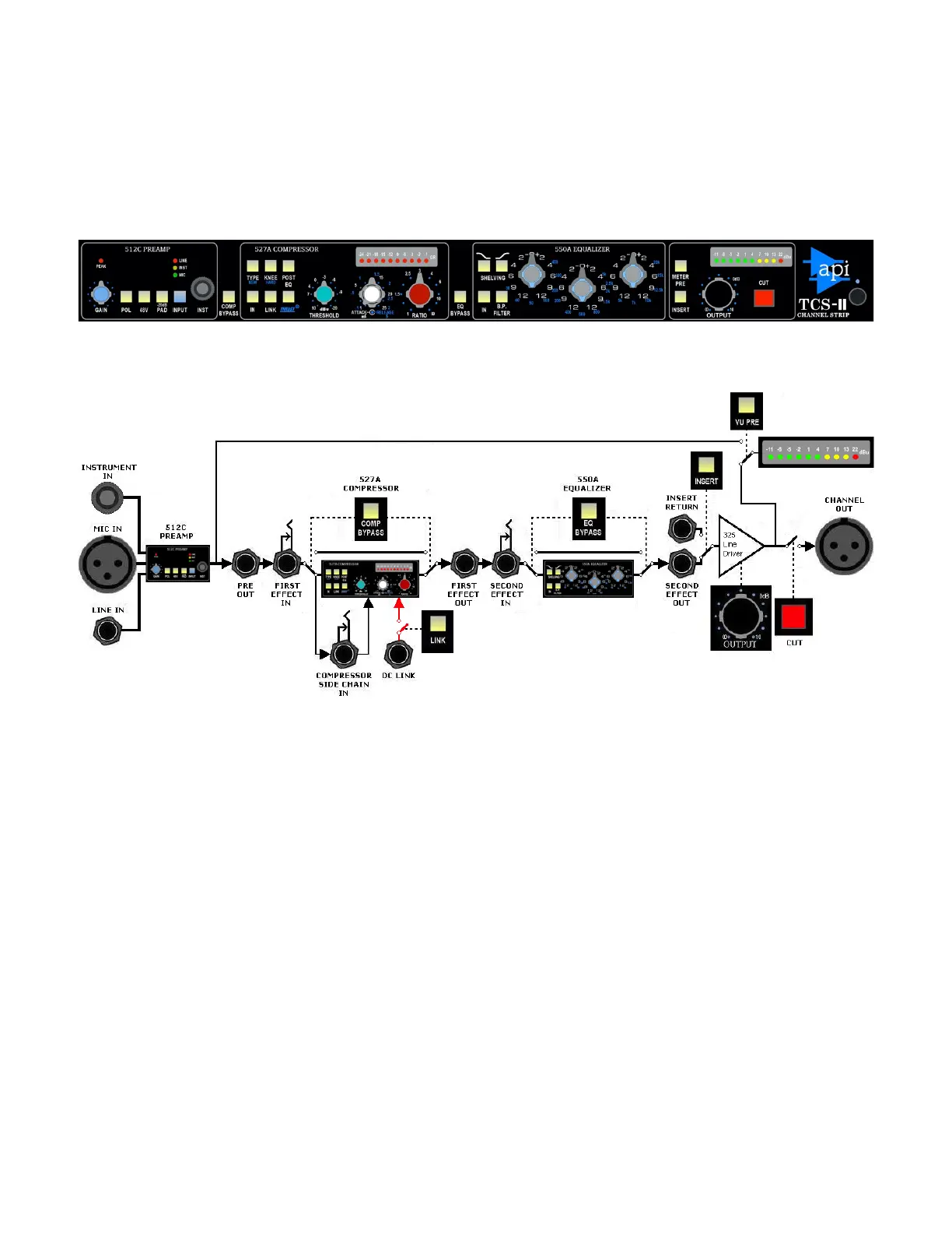
2.0 Signal Flow and Block Diagrams
2.1 Default Signal Flow
With no routing switches engaged, the default signal flow through the TCS-II is illustrated by the left-
to-right order of the unit’s front panel:
512C Preamp -----------> 527A Compressor ------------------> 550A Equalizer--> Insert --> 325 Output
The block diagram below illustrates the TCS-II signal flow with no switches engaged except the CUT
button. This is the “default” signal flow through the unit.
2.2 Alternate Signal Flows
The default signal flow can be modified in four (4) ways without patching:
• The 527A Compressor can be moved after the 550A Equalizer (POST EQ)
• The 527A Compressor can be hard bypassed (COMP BYPASS)
• The 550A Equalizer can be hard bypassed (EQ BYPASS)
• Insert Return can be engaged (INSERT)
Since each of these routing functions are independent of each other, multiple signal flow configurations
are possible. Combined with the open interfacing available on the rear panel, comprehensive and
flexible routing possibilities are available to meet most production needs.
2.2.1 Compressor Post Equalizer Signal Flow
Engaging the POST EQ switch will move the 527A Compressor to after the 550A Equalizer. When
the POST EQ switch is engaged, the signal flow will be as follows:
512C Preamp ---> 550A Equalizer ---> 527A Compressor ---> Insert ---> 325 Output
Bekijk gratis de handleiding van API Audio TCS-II, stel vragen en lees de antwoorden op veelvoorkomende problemen, of gebruik onze assistent om sneller informatie in de handleiding te vinden of uitleg te krijgen over specifieke functies.
Productinformatie
| Merk | API Audio |
| Model | TCS-II |
| Categorie | Niet gecategoriseerd |
| Taal | Nederlands |
| Grootte | 7243 MB |


