Advantech ICR-2413 handleiding
Handleiding
Je bekijkt pagina 24 van 44
ICR-2412
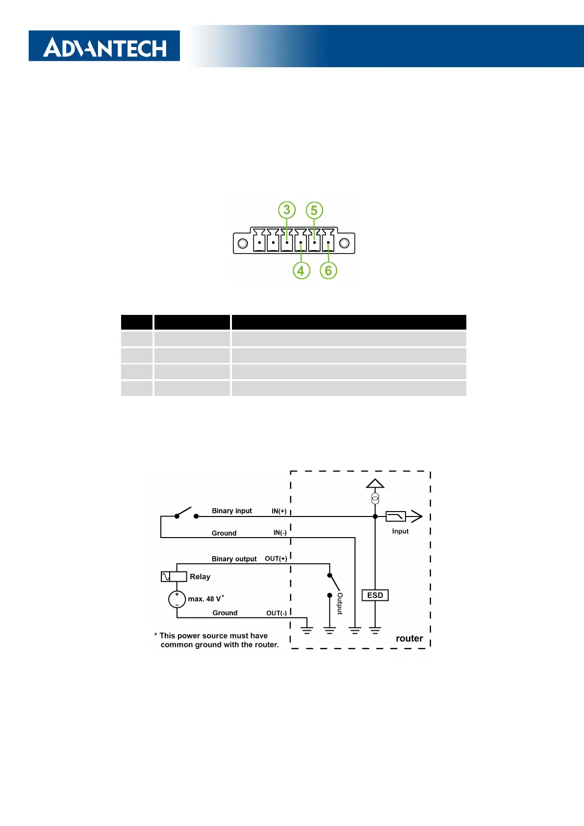
2.5 I/O Port Interfaces
The pins of I/O interface are physically connected to the 6-pin terminal block panel socket
located on the left panel. The pinout of one binary input and one binary output is shown in
Figure 16 and described in Table 7.
Figure 16: I/O Connector Pinout
Pin Signal mark Description
3 IN(+) The binary input (positive pole)
4 IN(-) The binary input (negative pole)
5 OUT(+) The binary output (positive pole)
6 OUT(-) The binary output (negative pole)
Table 7: I/O Ports Pinout
The I/O user interface is designed for binary input processing and binary output control.
For detailed electrical parameters see Chapter 4.6. The functional scheme of connection for
the binary input and binary output is in Figure 17.
Figure 17: Functional Scheme of the Binary Interface
18
Bekijk gratis de handleiding van Advantech ICR-2413, stel vragen en lees de antwoorden op veelvoorkomende problemen, of gebruik onze assistent om sneller informatie in de handleiding te vinden of uitleg te krijgen over specifieke functies.
Productinformatie
| Merk | Advantech |
| Model | ICR-2413 |
| Categorie | Niet gecategoriseerd |
| Taal | Nederlands |
| Grootte | 5608 MB |


