Advantech ICR-2413 handleiding
Handleiding
Je bekijkt pagina 23 van 44
ICR-2412
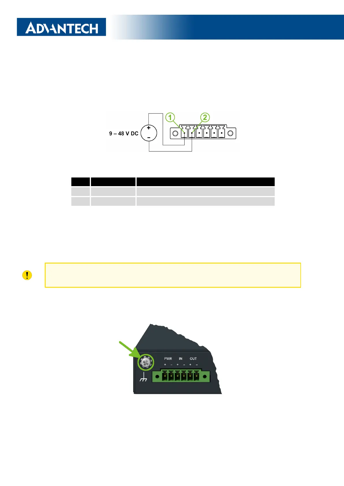
2.4 Power Supply
The pins of power supply are physically connected to the 6-pin terminal block panel socket
located on the left panel. The connection of power supply is shown in Figure 14 and described
in Table 6.
Figure 14: Connection of Power Supply
Pin Signal mark Description
1 PWR(+) Positive pole of DC supply voltage (+9 to +48 V DC)
2 PWR(-) Negative pole of DC supply voltage
Table 6: Power Supply Pinout
Required power supply voltage for the router is between +9 V and +48 V DC, see the
connection scheme on Figure 14. Protection against reversed polarity without signaling is
built into the router. For correct operation it is necessary that the power source is able to
supply a peak current of 1 A.
Unit has to be supplied by a power supply specified as a Limited Power Source (LPS) or
CEC/NEC Class 2 source of supply.
The metal case of the router is not connected to the negative pole of the power sup-
ply (common pole). If recommended for the installation environment, protect the router by
grounding it properly by the grounding screw, see Figure 15.
Figure 15: Position of the Grounding Screw
17
Bekijk gratis de handleiding van Advantech ICR-2413, stel vragen en lees de antwoorden op veelvoorkomende problemen, of gebruik onze assistent om sneller informatie in de handleiding te vinden of uitleg te krijgen over specifieke functies.
Productinformatie
| Merk | Advantech |
| Model | ICR-2413 |
| Categorie | Niet gecategoriseerd |
| Taal | Nederlands |
| Grootte | 5608 MB |


