Advantech AIIS-1882 handleiding
Handleiding
Je bekijkt pagina 22 van 40
AIIS-1882 User Manual 12
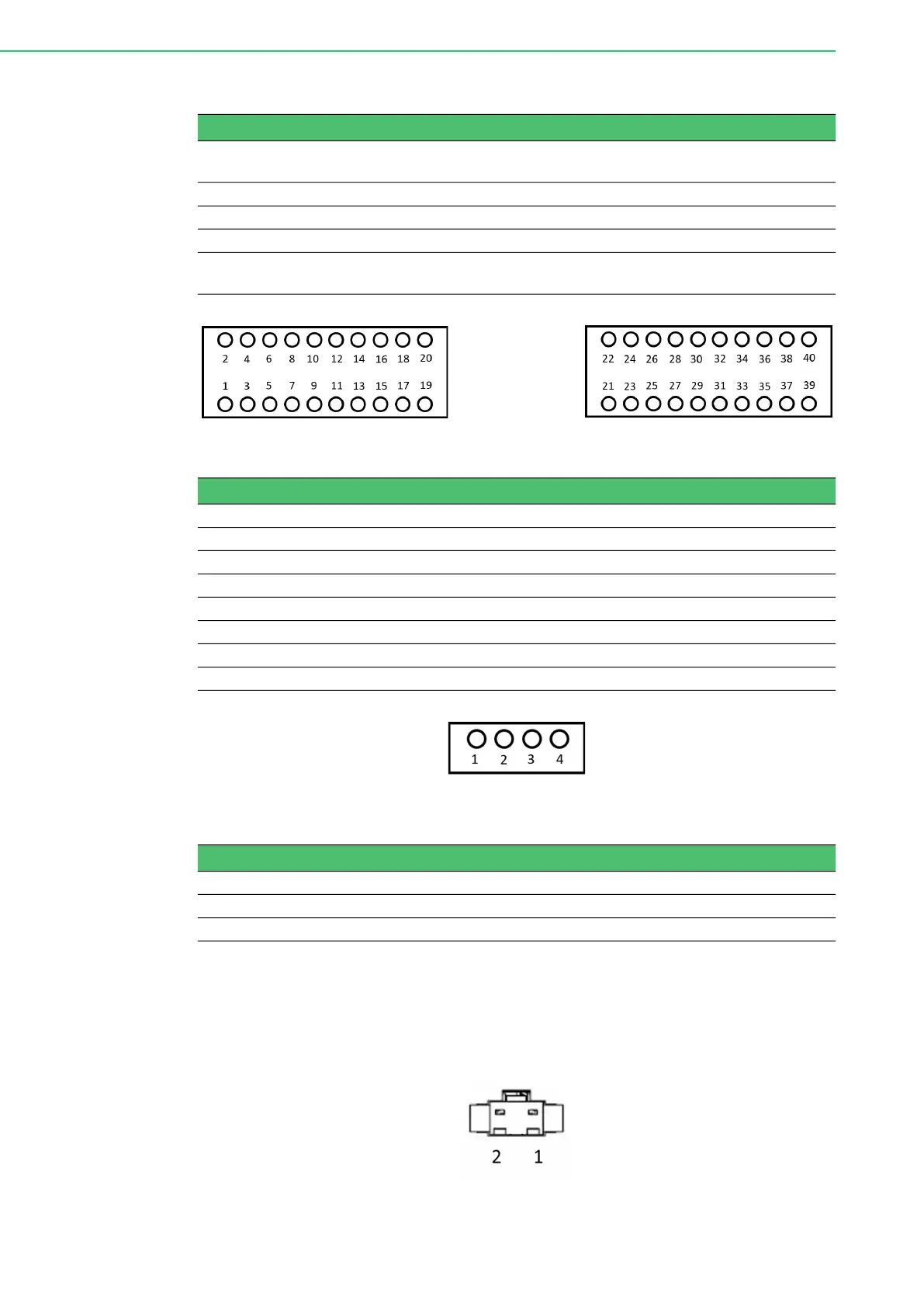
Figure 2.11 Pin assignments of digital I/O and triggers
Figure 2.12 Pin assignment of external power
2-pin Lighting Connectors (LT0~LT3)
The connector that AIIS-1882 provides by default is a 2-pin connector. If the lighting
to be connected with it is 3-pin, then 3-pin accessories (front panel and cable) need
to be purchased separately. The pin definition for a 2-pin connector is shown below:
Figure 2.13 Pin assignment of 2-pin lighting connector
Table 2.1: Connectors
Connector Name Description Connector Number
on Board
DI/TRG Connector for digital input and trigger input CN9
DO Connector for digital output CN5
DC IN External power for lighting output 1~4 CN14
LT n Lighting output n, n = 1~4, connected via 3-pin
cable to be assembled on the front panel
CN10~CN13
Table 2.2: Pin assignment of digital I/O and trigger
Pin name Description Pin Number
DICOM Common pin for isolated digital input 1, 2
IDI n Isolated digital input n, n = 0~11 3~14
Trigger n Trigger input for lighting n, n = 0~3 15~18
NC Reserved 19, 20
DOCOM Common pin for isolated digital output (see signal connection) 21, 22, 39, 40
IDO n Isolated digital output n, n = 0~15 23~38
ISOGND Ground connection for isolated digital output 39, 40
Table 2.3: Pin assignment of external power
Pin Name Description Pin Number
Power V+ Positive pin for external power input 2, 3
Power V- Negative pin for external power input 1, 4
Bekijk gratis de handleiding van Advantech AIIS-1882, stel vragen en lees de antwoorden op veelvoorkomende problemen, of gebruik onze assistent om sneller informatie in de handleiding te vinden of uitleg te krijgen over specifieke functies.
Productinformatie
| Merk | Advantech |
| Model | AIIS-1882 |
| Categorie | Niet gecategoriseerd |
| Taal | Nederlands |
| Grootte | 5165 MB |


