Handleiding
Je bekijkt pagina 20 van 96
6
❷ Installaon
2.1 I Selecng the locaon
• The appliance must be installed in a dry venlated plant room with no pool maintenance
products stored nearby.
• The appliance must be installed before any water treatment system.
• The water inlet of this appliance shall not be connected to inlet water obtained from any other
water heang system.
• The appliance must be posioned vercally and held by piping supported by brackets on either side of the
heater,
• The appliance must be secured to the wall using 4 screws (not provided, see aachment points in the
rear view § "1.3 I Dimensions and marking"),
IMPORTANT: Do not aach the appliance using adhesive tape.
• Leave a free space around the appliance to facilitate its installaon and maintenance,
• Preferably, the appliance should be installed at the low point so that it is always full of water,
• The water treatment system must be installed at the low point aer the heater to prevent chlorine from
owing back into the heater.
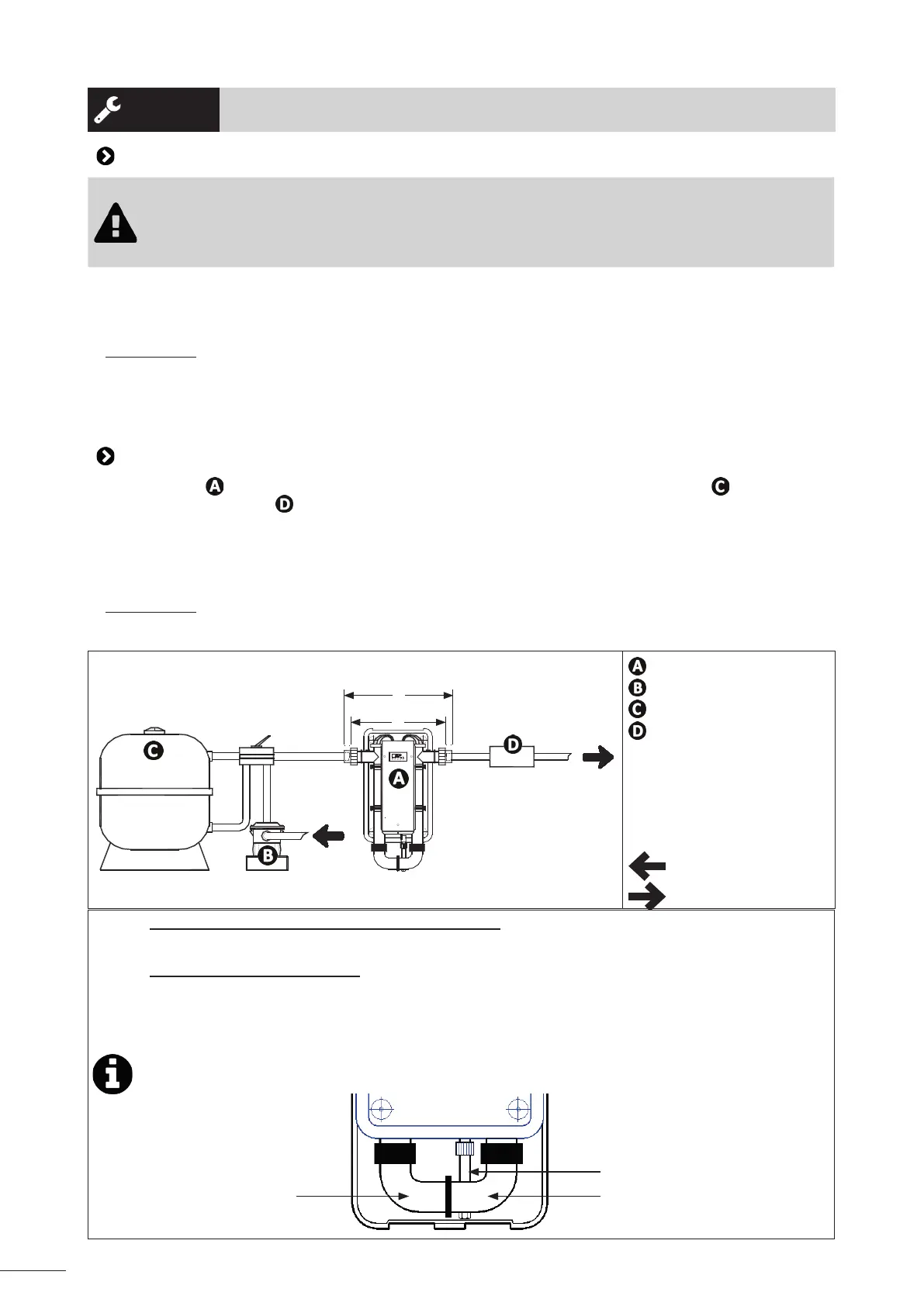
2.2 I Hydraulic connecons
• The appliance must be connected in line to the pool's ltraon circuit aer the lter and before the
water treatment system (see diagram below).
• The connecon can be made using a PVC pressure pipe:
- directly if the water ow falls within the range 5 m
3
/h minimum to 22 m
3
/h maximum,
- via a by-pass if the ow rate is greater than 22 m³/h, or for easier maintenance of the appliance,
• 1/2 union ngs (Ø50 internal female coupling and Ø63 external male coupling) are provided for
connecon to the ltraon circuit with Ø50 or Ø63 PVC piping.
IMPORTANT: Do not re-use worn couplings and do not connect the outlet pipe to any tap or ng other
than those specied.
• Check the correct clamping of the hydraulic connectors and that there are no leaks.
E
F
: RE/U electric heater
: Filtraon pump
: Filter
: Water treatment
E: 540 mm (±1 mm) in the
case of filtration via Ø50 PVC
piping.
F: 600 mm (±1 mm) in the
case of filtration via Ø63 PVC
piping.
: Pool inlet
: To the discharge port
Informaon: ltraon circuit with Ø63 PVC piping
• To connect the appliance, provide an adapter (internal Ø of 63).
Informaon: direcon of ow
• The heater is provided for a water ow circulang from le to right as shown by the "water
inlet" and "water outlet" symbols visible on the appliance.
• If necessary, reverse the direcon of ow as follows:
- invert the digital regulaon thermostat and safety thermostat sensors. The regulaon
thermostat must be located at the heater inlet and the safety sensor at the outlet.
- rotate the 2 bends + ow switch together by half a turn (see diagram below).
Bend Bend
Flow switch
Bekijk gratis de handleiding van Zodiac RE/U, stel vragen en lees de antwoorden op veelvoorkomende problemen, of gebruik onze assistent om sneller informatie in de handleiding te vinden of uitleg te krijgen over specifieke functies.
Productinformatie
| Merk | Zodiac |
| Model | RE/U |
| Categorie | Heater |
| Taal | Nederlands |
| Grootte | 17595 MB |

