Yamaha Rio3224-D3 handleiding
Handleiding
Je bekijkt pagina 9 van 44
Controls and Functions
Rio3224-D3 Rio1608-D3 Reference Manual
9
Controls and Functions
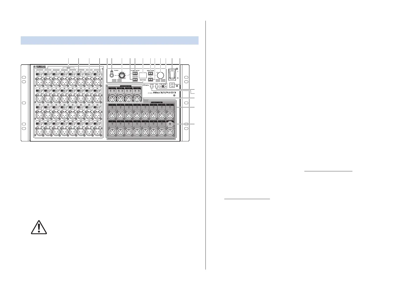
Front Panel
1 [INPUT] 1–32 {1–16}
These are balanced XLR 3-hole chassis input connectors that enable you to input analog
signals to each channel. The rated input level range is from −62 dBu to +10 dBu.
Phantom power of +48 V can be supplied to devices that require it via the input
connectors.
2 [+48V]
These indicators light when +48 V phantom power is turned ON for the corresponding
input channels. On/off switching is controlled from this unit's front panel display, or
from a supported device. No phantom power will be supplied, however, if the
[+48V ACTIVE] switch is OFF, even if phantom power to individual channels is turned
ON (the [+48V] indicators will flash). If a serious error occurs on the unit, these indicators
will light or flash on all channels.
WARNING
To prevent possible damage to speakers, make sure that power amplifiers and/or powered
speakers are turned OFF when switching phantom power ON or OFF. In addition, make sure that
all output controls on the digital mixing console are set to minimum when turning phantom power
ON or OFF. Sudden high level peaks caused by the switching operation can damage equipment
as well as the hearing of those present.
NOTICE
• If phantom power is not required, you must turn OFF the [+48V ACTIVE] switch or the phantom
power setting.
• When turning phantom power ON, make sure that no equipment other than phantom-powered
devices such as condenser microphones are connected to the corresponding [INPUT]
connectors. Applying phantom power to a device that does not require phantom power can
damage the connected device.
• Do not connect or disconnect a device to an [INPUT] connector while phantom power is applied.
Doing so can damage the connected device and/or the unit itself.
3 [SIG] (Signal)
These indicators light green when the input or output signal applied to the
corresponding channel reaches or exceeds −40 dBFS.
If a serious error occurs on the unit, these indicators will light or flash on all channels.
4 [PEAK]
These indicators light red when the signal level of the corresponding input channel
reaches or exceeds −3 dBFS.
If a serious error occurs on the unit, these indicators will light or flash on all channels.
5 [PHONES] socket
This is a headphone socket that outputs assigned audio signals (INPUT/OUTPUT). You
can view the signal assignments and parameter values on the PHONES screen.
6 [PHONES] level knob
This knob adjusts the level of the signal output from the [PHONES] socket.
7 [PHONES/METER]
Press this key repeatedly to display the PHONES screen or one of the METER screens. The
screen changes each time you press the key.
Press and hold to clear PEAK HOLD. (See “Clearing the PEAK HOLD
” on page 24.)
8 [FUNCTION]
Press this key to recall the registered function screen.
Related link(s)
“FUNCTION LIST Screen
”
9 Display
This shows information such as the parameter values of each channel's head amp, or
error and status indications.
1 5 6 7 A
9
G
I
D
E
J
2 3 4
C F80 B H
3
Bekijk gratis de handleiding van Yamaha Rio3224-D3, stel vragen en lees de antwoorden op veelvoorkomende problemen, of gebruik onze assistent om sneller informatie in de handleiding te vinden of uitleg te krijgen over specifieke functies.
Productinformatie
| Merk | Yamaha |
| Model | Rio3224-D3 |
| Categorie | Niet gecategoriseerd |
| Taal | Nederlands |
| Grootte | 5838 MB |


