Yaesu FT-847 handleiding
Handleiding
Je bekijkt pagina 27 van 108
25
FT-847 OPERATING MANUAL
(32) Keypad
The keypad is used for direct frequency entry during
VFO operation. Secondary functions allow control of
certain repeater, scanning, and frequency navigation
functions.
(33) SHIFT Control
This control is used to adjust the receiver’s IF SHIFT
feature, which tunes the 455 kHz IF relative to the
center frequency of the selected IF filter (in all modes
except FM). The default position of this control is 12
o’clock, and an adjustment range of about ±1.2 kHz is
provided (the pitch of the incoming signals will not
change, however).
(34) DIG. FIL Switch
Pressing this switch activates the receiver’s DSP fil-
ters. When the DSP is activated, the “
DIG.FIL
” icon
will appear on the display panel.
(35) DIGITAL FIL
(LOW CUT/HIGH CUT Controls)
These controls adjust the passband cutoff frequencies
of the receiver’s HIGH CUT and LOW CUT DSP
filters in the SSB, AM, and FM modes. The inner con-
trol adjusts the LOW-CUT characteristics, while the outer
control adjusts the HIGH-CUT characteristics.
(36) NOTCH Switch
This is the ON/OFF switch for the beat-canceling DSP
NOTCH filter.
(37) NR Switch
This is the ON/OFF switch for the DSP NOISE REDUC-
TION filter. The level of DSP Noise Reduction is set
via Menu #11 (see page 85).
(38) CLAR Switch
Pressing this switch activates the RX CLARIFIER
(“RIT”), which provides offset tuning from the Main
VFO frequency. When this feature is enabled, the
“
CLAR
” icon will appear on the display panel. The
SUB-TUNE knob is used for Clarifier adjustment, and
the available offset range is ±9.99 kHz.
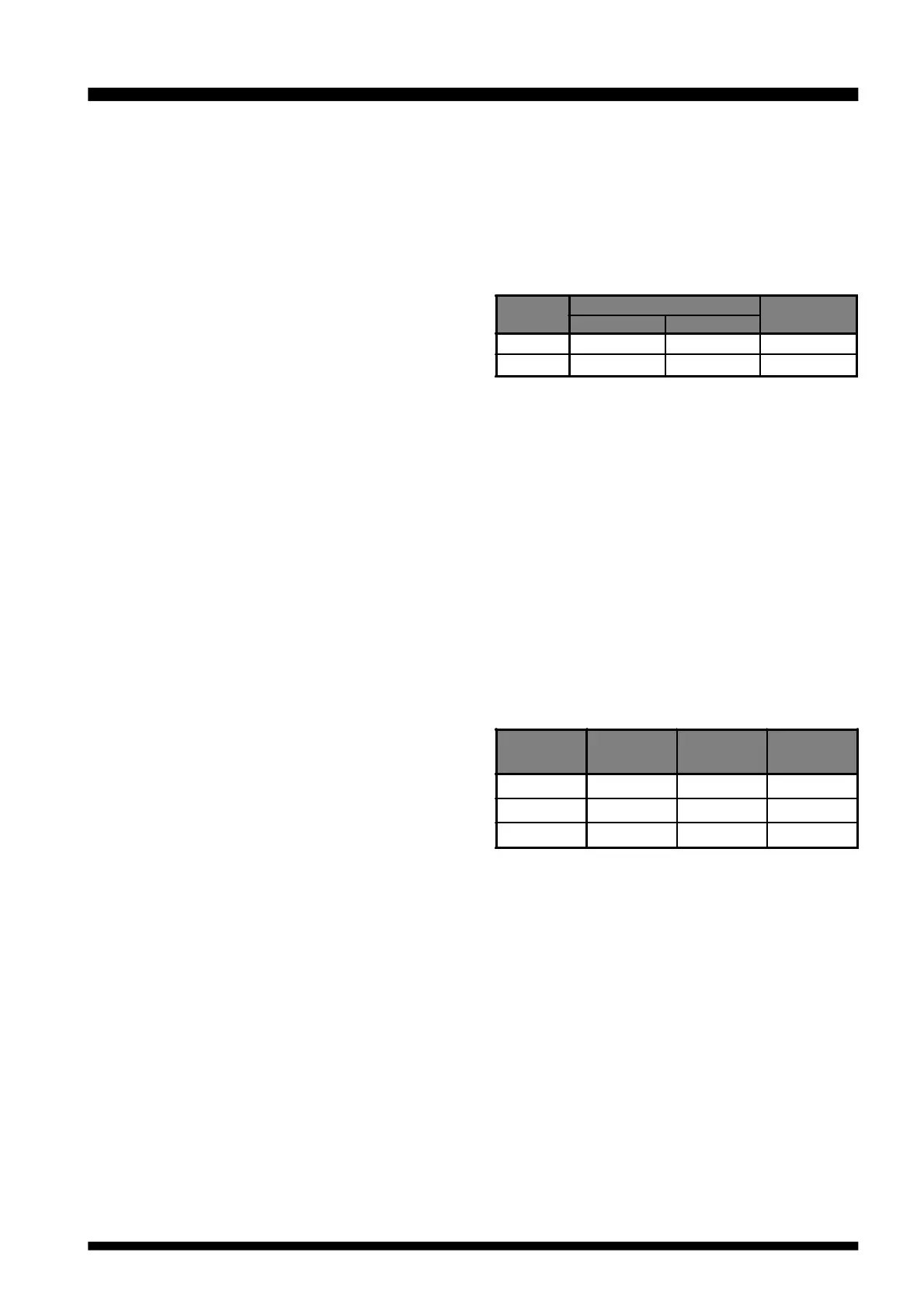
(39) SUB-TUNE Knob
This knob is the tuning dial which controls the fre-
quency of the Sub VFO. Clockwise rotation of the dial
increases the frequency, while counter-clockwise ro-
tation decreases the frequency.
The tuning steps are defined by the setting of Menu
#2, which also sets the steps for the Main Tuning Dial.
The default tuning steps are shown below:
(40) MENU Switch
Pressing this switch momentarily activates the “MENU”
mode, which allows customization of many aspects of
transceiver configuration.
(41) MEM/VFO CH Knob
When the VFO mode is active, this detented knob be-
comes a “channelized” tuning control, which allows
quick navigation up and down the band.
This knob selects the Memory Channel when the
Memory mode is active.
The tuning steps for the MEM/VFO CH knob (when
operating in the “VFO” mode) may be set via the Menu
system. The default steps are:
Ú: Depends on transceiver version (USA, European, etc.)
These steps may be set individually for the HF, 50
MHz, 144 MHz, and 430 MHz bands; see page 34 for
details.
(42) QMB RCL Switch
This switch is used for one-touch recall of the Quick
Memory Bank memory.
(43) QMB STO Switch
This switch is used for storing a Main VFO frequency
into the QMB memory register.
Front Panel Controls & Switches
Mode
Available Steps
Default
NORMAL FAST
Step
SSB/CW
0.1, 1, 10 Hz 1, 10, 100 Hz 1 Hz/10 Hz
AM/FM
10 Hz 100 Hz 10 Hz/100 Hz
Operating
Mode
HF Bands VHF Bands UHF Bands
SSB/CW 2.5 kHz 2.5 kHz 2.5 kHz
AM 5 kHz 5 kHz 5 kHz
FM 5 kHz
Ú Ú
Bekijk gratis de handleiding van Yaesu FT-847, stel vragen en lees de antwoorden op veelvoorkomende problemen, of gebruik onze assistent om sneller informatie in de handleiding te vinden of uitleg te krijgen over specifieke functies.
Productinformatie
| Merk | Yaesu |
| Model | FT-847 |
| Categorie | Niet gecategoriseerd |
| Taal | Nederlands |
| Grootte | 17150 MB |


