Williams Sound IR T2 handleiding
Handleiding
Je bekijkt pagina 8 van 16
8
IR T2 Infrared Transmitter
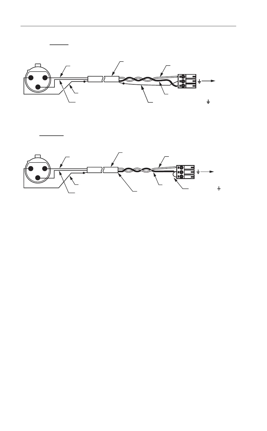
Figure 3: Balanced line out (XLR) to IR T2 line input (Phoenix style connector)
1 23
FEMALE XLR
RED (IN PHASE [+])
RED
2 CONDUCTOR
WITH SHIELD
BLACK (SIGNAL [-])
BLACK CONNECTED TO -
TO IR T2
SHIELD CONNECTED TO GND
ON IR T2 CABLE END
1= SHIELD, 2= RED (SIGNAL IN PHASE), 3= BLACK (SIGNAL)
PHOENIX
STYLE CONNECTOR
3-Pin, 0.15” Pitch
+
-
BALANCED AUDIO
SHIELD
1 23
FEMALE XLR
RED (IN PHASE [+])
RED
2 CONDUCTOR
WITH SHIELD
BLACK (SIGNAL [-])
BLACK
TO IR T2
SHIELD NOT CONNECTED
ON IR T2 CABLE END
1= SHIELD, 2= RED (SIGNAL IN PHASE), 3= BLACK (SIGNAL)
PHOENIX
STYLE CONNCTOR
3-Pin, 0.15” Pitch
+
-
UNBALANCED AUDIO
A509
SHIELD
USE SHORT WIRE TO
CONNECT - TO
Figure 4: Unbalanced line out (XLR) to IR T2 line input (Phoenix style connector)
1 23
FEMALE XLR
RED (IN PHASE [+])
RED
2 CONDUCTOR
WITH SHIELD
BLACK (SIGNAL [-])
BLACK CONNECTED TO -
TO IR T2
SHIELD CONNECTED TO GND
ON IR T2 CABLE END
1= SHIELD, 2= RED (SIGNAL IN PHASE), 3= BLACK (SIGNAL)
PHOENIX
STYLE CONNECTOR
3-Pin, 0.15” Pitch
+
-
BALANCED AUDIO
SHIELD
1 23
FEMALE XLR
RED (IN PHASE [+])
RED
2 CONDUCTOR
WITH SHIELD
BLACK (SIGNAL [-])
BLACK
TO IR T2
SHIELD NOT CONNECTED
ON IR T2 CABLE END
1= SHIELD, 2= RED (SIGNAL IN PHASE), 3= BLACK (SIGNAL)
PHOENIX
STYLE CONNCTOR
3-Pin, 0.15” Pitch
+
-
UNBALANCED AUDIO
A509
SHIELD
USE SHORT WIRE TO
CONNECT - TO
Summing an unbalanced stereo line-level source to a single mono input
If using a stereo source for an input, the stereo signal will be combined to mono, and heard in
mono, on the A or B channel of the IR T2.
The + and - phoenix terminals on the IR T2 are each tied internally to single dierential
amplifiers.
Proper Wiring (Yes circle in Figure 5): The L+ cable can be connected directly to the +
connector. The R + cables should not be used at all.
When summing for stereo to mono only, the resistors, along with the jumper between -
and ground, are necessary to allow the left and right signals to be summed before being
preamplified by the single dierential (single-ended) amplifier inside the IR T2.
Improper Wiring (No circle in Figure 5): If the left and right positive leads from the source
were connected to the + and - pins on the Phoenix style connector, and their grounds
(shields) were connected to the ground terminal, the result would be the dierence of the left
and right channels. The main part of the audio signal (what is common to both the left and
right channels) would be missing, as this is thrown away during dierential amplification. The
dierence is very little, resulting in a very low input signal. In this case, most of the original
audio would not be heard!
Bekijk gratis de handleiding van Williams Sound IR T2, stel vragen en lees de antwoorden op veelvoorkomende problemen, of gebruik onze assistent om sneller informatie in de handleiding te vinden of uitleg te krijgen over specifieke functies.
Productinformatie
| Merk | Williams Sound |
| Model | IR T2 |
| Categorie | Niet gecategoriseerd |
| Taal | Nederlands |
| Grootte | 881 MB |

