Williams Sound IR T2 handleiding
Handleiding
Je bekijkt pagina 6 van 16
6
IR T2 Infrared Transmitter
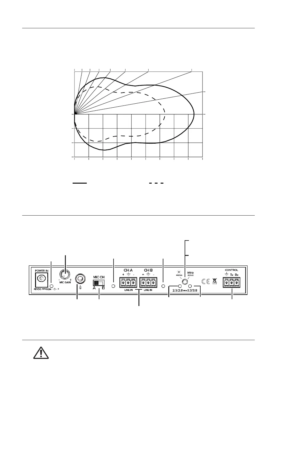
Figure 1: Receiver coverage area with IR T2 transmitter in single channel mode.
0°
10°
0ft/0m
25ft/8m
50ft/15m
75ft/23m
IR T2 Coverage Pattern
0ft/0m
25ft/8m
50ft/15m
75ft/23m
100ft/30m
125ft/38m
150ft/46m
175ft/53m
200ft/61m
225ft/69m
20°
30°
40°
50°
60°
70°
80°
90°
RX22-4 Receiver
RX20 Receiver
Control Panel
Figure 2: IR T2 rear view
MIC
CHANNEL
SELECTOR
CH A AUDIO
LEVEL INDICATOR
(YELLOW)
CH B AUDIO
LEVEL INDICATOR
(YELLOW)
AUDIO LINE IN
CARRIER
INDICATOR LED
(2.3,2.8)
CARRIER
INDICATOR LED
(3.3,3.8)
LED BACK PANEL LIGHTS ON/OFF
(PRESS AN RELEASE)
CHANGE CARRIER FREQUENCY
(PRESS AND HOLD FOR 3 SECONDS)
RS-232 CONTROL
AND MONITORING
BUS
MICROPHONE
ADJUSTMENT
POWER
INDICATOR
(GREEN)
MIC
IN
Connecting Power
WARNING: MAINS VOLTAGE MUST NOT FALL BELOW 100 VAC, OR SYSTEM
PERFORMANCE WILL BE GREATLY REDUCED. UNIT MAY ENTER RESET
MODE UNTIL POWER IS RESTORED.
1. Plug the power supply output cord into Power In on the IR T2.
2. Attach a line cord to the power supply.
3. Plug the power supply into the AC outlet. Supplied TFP: 100-240 VAC IN, 50 / 60 Hz.
This system is designed for class 2, low-voltage wiring. Always follow local electrical codes
when using low-voltage wiring.
Bekijk gratis de handleiding van Williams Sound IR T2, stel vragen en lees de antwoorden op veelvoorkomende problemen, of gebruik onze assistent om sneller informatie in de handleiding te vinden of uitleg te krijgen over specifieke functies.
Productinformatie
| Merk | Williams Sound |
| Model | IR T2 |
| Categorie | Niet gecategoriseerd |
| Taal | Nederlands |
| Grootte | 881 MB |

