Wells MDW200 handleiding
Handleiding
Je bekijkt pagina 23 van 28
2M-Z21001 Rev- Owner's Manual for IRCS4 Impingement/Radiant Split-Belt Conveyor Toaster
19
2M-Z21876 Rev- Owner’s Manual for MDW Modular Dry Well
WELLS BLOOMFIELD, LLC
•
www.wellsbloomf ield.com
265 Hobson Street • Smithville, Tennessee 37166
Telephone 888 356 5362 • Fax 314 781 5445
The unit’s overall depth is 12.125 inches (308 mm) and will
sit approximately 11.75 inches (298 mm) below the counter
surface depending on counter thickness.
MDW200 Modular Dry Well
Installation Instructions
Printed in the U.S.A. • 2M-Z20756 •
Rev A • 03.2017
The owner is responsible for proper installation as
described above. Please refer to the owner’s manual
for information regarding installation or use.
Do not disconnect the control box from the modular unit.
i. Remove the knobs and faceplate from the control box. Pass the
control box through the countertop cutout, and then through
the apron cutout. This will require the box to be rotated so the
mounting tabs clear the hole. Next, lower and position the
modular section into countertop cutout.
ii. Before final seating of modular section to countertop, apply
a bead of silicone sealant to the underside of the grey gasket
material supplied on the mounting flange. From underneath,
insert screwdriver into the slots in the Wellslok frame and twist
clockwise to move the ears outward as required to secure the
flange tightly to countertop.1
iii. Mount the control box to apron cutout using #10 sheet metal [or
wood] screws to the facing side where the holes were drilled.
iv. Run wiring through the conduit knockout to the terminal block,
making connection as shown in the unit’s wiring diagram to the
correct power source.
v. Mount the front panel onto the control box using the provided
hardware and place the knobs/covers on. At this point, you should
be able to power on the unit and check for proper operation.
Do not install closer than 4.125 inches (105 mm) to front wall,
one [1] inch (25 mm) to back and side walls, and 6.75 inches
(171 mm) to a surface below the unit. If storage is to be used
underneath, it is recommended that a bae be placed 8.5
inches (216 mm) below the unit to avoid contact with elevated
temperatures. The unit will need to be accessible from the
bottom after installation is complete.
A proper electrical connection based on the units electrical
specifications will be necessary for installation. This must
be wired and connected by a licensed electrician. Electrical
installation will need to pass local electrical codes.
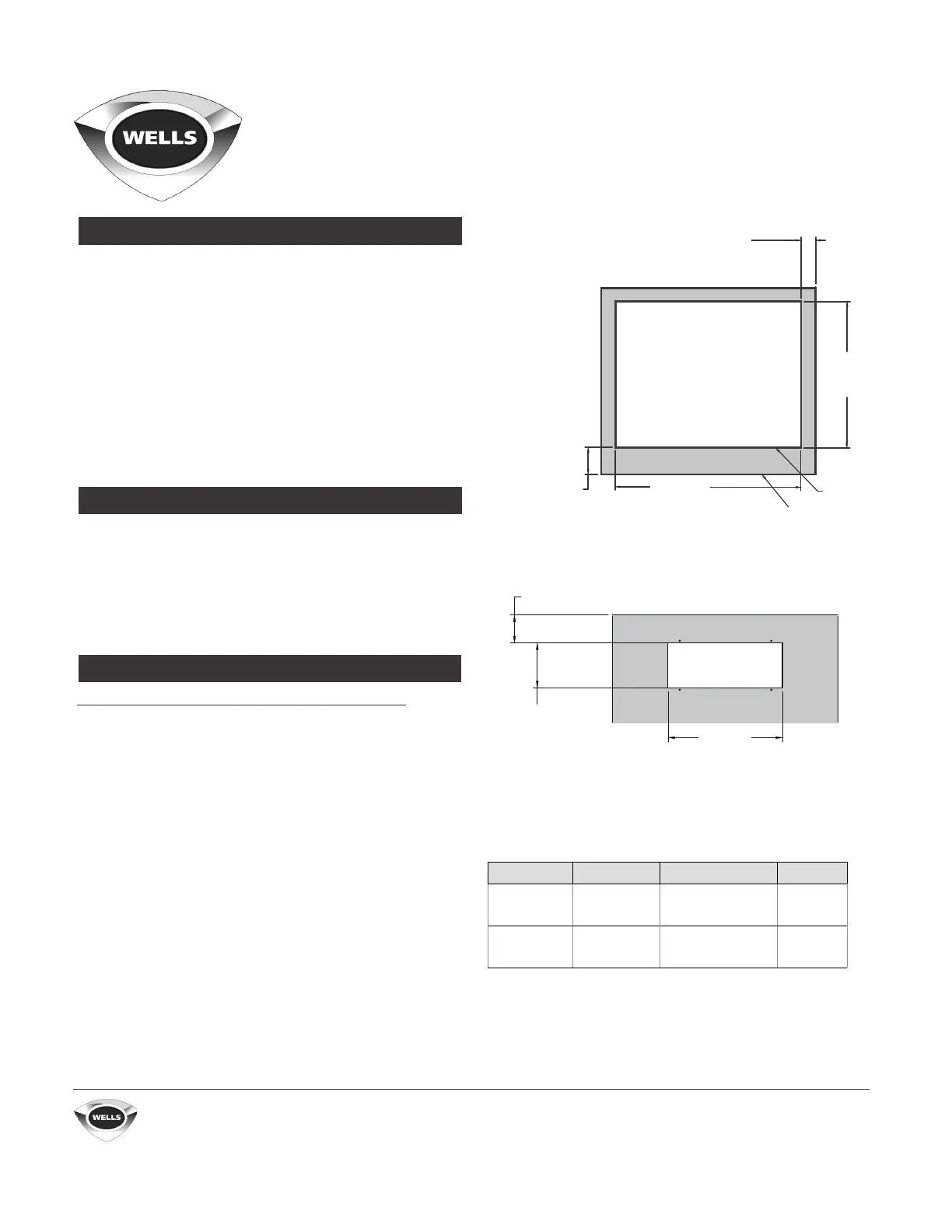
i. Lay out cutout dimensions on countertop and front apron.
ii. Lay out control panel mounting holes in counter apron using
the control box as a template. The mounting holes should be
0.144 inch (3.7 mm) in diameter [drill size 27].
iii. Cut out the holes. On many countertops, reinforcement may
be needed to stiffen the countertop.
INSTALLATION INSTRUCTIONS
INSTALLATION REQUIREMENTS
FABRICATION
MODEL TOTAL kW VOLTS, PHASE AMPS
MDW200 1.22
1.6
208, 1Φ
240, 1Φ
5.9
6.7
MDW200R 1.9
2.5
208, 1Φ
240, 1Φ
9.1
10.4
4.125 in. (105 mm)
minimum clearance
on control side
2.25 in. (57 mm)
minimum clearance
on non-control side
cutout
22.5 in.
(572 mm)
28.5 in.
(724 mm)
countertop
The supply wire will need to be the correct gauge as described by
the National Electrical Code and be rated to at least 167°F (75°C).
1 Wellslok adapter kits [2 required] will use hex screws to tighten
and allow installation on countertops up to 1.5 inches (38 mm) thick.
3.125 in.
(79 mm)
5 in.
(127 mm)
12.875 in.
(327 mm)
Bekijk gratis de handleiding van Wells MDW200, stel vragen en lees de antwoorden op veelvoorkomende problemen, of gebruik onze assistent om sneller informatie in de handleiding te vinden of uitleg te krijgen over specifieke functies.
Productinformatie
| Merk | Wells |
| Model | MDW200 |
| Categorie | Niet gecategoriseerd |
| Taal | Nederlands |
| Grootte | 3861 MB |


