Vivotek IP9191-HT-V2 handleiding
Handleiding
Je bekijkt pagina 11 van 460
VIVOTEK
User's Manual - 11
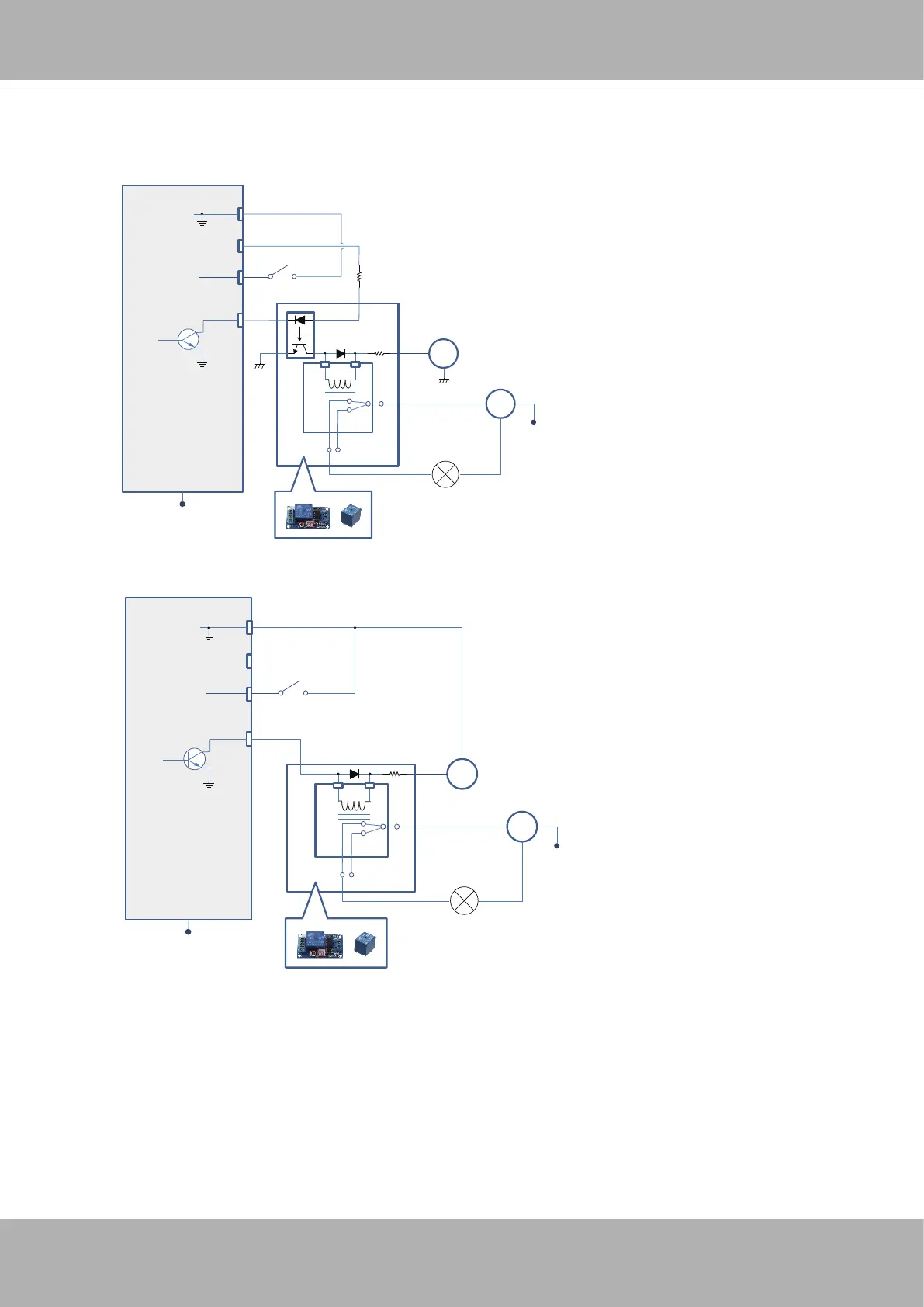
DI/DO Diagram
DI-
DO+
DI+
DO-
Switch
External Device
External DC power
Dry contact with external DC power source to supply a relay. Dry contact is the safest connecon
to protect devices.
NC
NO
Relay
Photo
Coupler
DC
DC 0V
DC 0V
External AC power
with Protected Eart
h
AC
PE
PE
DI-
DO+
DI+
DO-
Switch
External Device
External DC power
Wet contact with external DC power source to supply a relay.
NC
NO
Relay
DC
External AC power
with Protected Earth
AC
PE
PE
DC 0V
1. The DO+ pin provides 5V output voltage, and the max. load is 50mA.
2. The max. voltage for DO- pins is 30VDC (External power).
In order to control AC devices, the above diagram can be taken in consideration. The
diagram uses a relay to control the ON/OFF condition of the AC device.
3. An external relay can be triggered by using DO+ or by an external power source,
depending on the type of relay you use.
4. In case of using an individual relay (instead of using a relay module), for protection
against voltage or current spikes, a transient voltage suppression diode must be
connected in parallel with the inductive load.
Bekijk gratis de handleiding van Vivotek IP9191-HT-V2, stel vragen en lees de antwoorden op veelvoorkomende problemen, of gebruik onze assistent om sneller informatie in de handleiding te vinden of uitleg te krijgen over specifieke functies.
Productinformatie
| Merk | Vivotek |
| Model | IP9191-HT-V2 |
| Categorie | Bewakingscamera |
| Taal | Nederlands |
| Grootte | 77587 MB |


