Vimar RS05 handleiding
Handleiding
Je bekijkt pagina 19 van 32
17
VIMAR group
M
System set-up
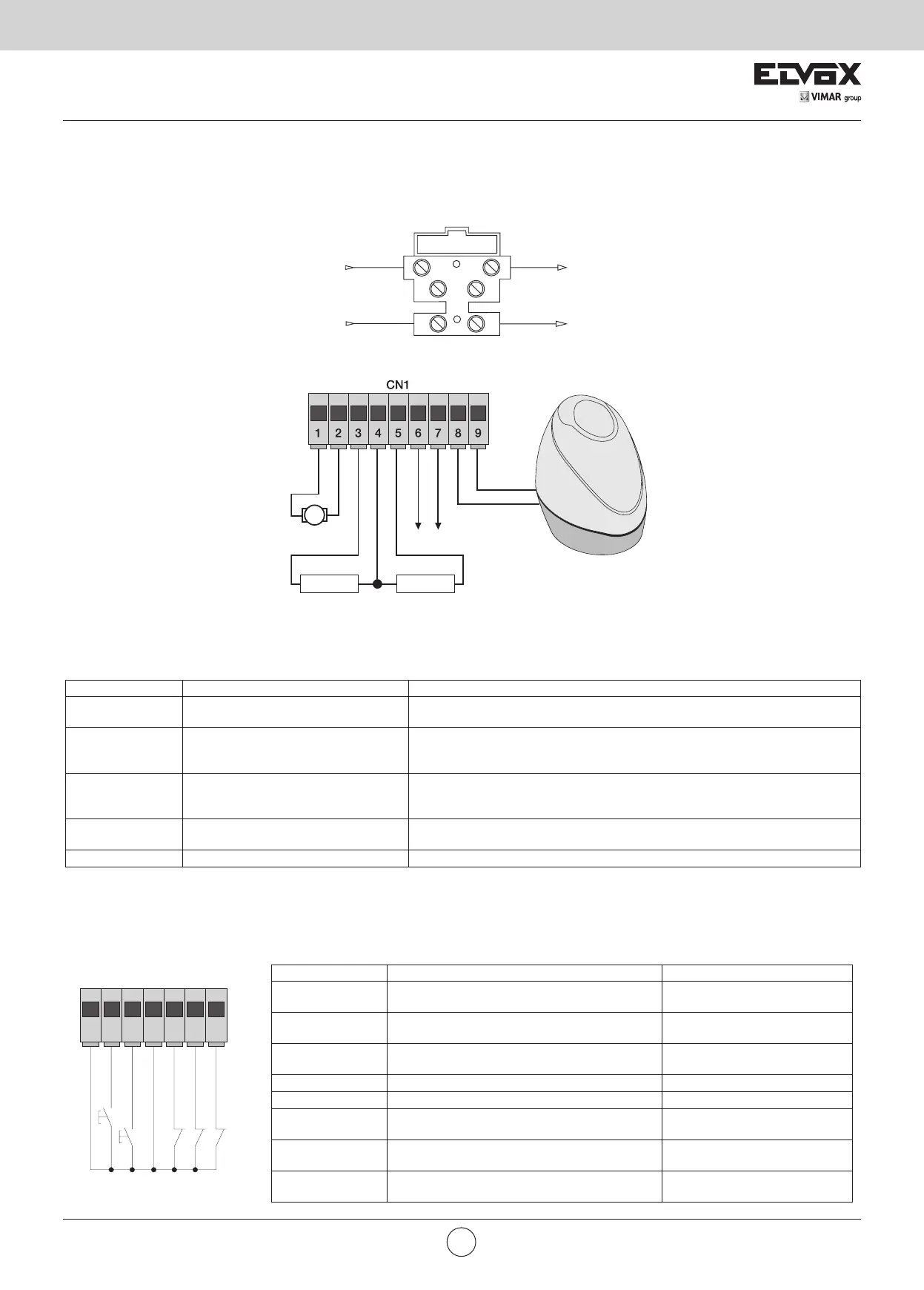
4.1 Power supply line wiring
Inside the transformer compartment there is a terminal with a 2 AT protection fuse, connect the phase in the corresponding pole to the fuse.
4.2 Wiring for flashing light, courtesy light and gate movement warning light
Terminals Description Function
1-2 Motor output Output for controlling electric motor 24 Vdc rated power 50 W
(terminal number 1 white, terminal number 2 brown)
3-4 Courtesy light or second radio channel Output 24 Vdc maximum load 85 mA, can be programmed as a timed output
(60seconds) or second radio channel output, see dip switch number 6
(3 = GND / 4 = +24 Vdc).
4-5 Warning light output Output 24 Vdc maximum load 85 mA, flashes slowly when opening, on with
stationary open gate, flashing fast when closing and off with gate closed (4 = 24
Vdc / 5 = GND).
6-7 Accessories power supply output Output 24 Vdc maximum 300 mA for supplying the photocells and accessories
(6 = +24 Vdc, 7= GND)
8-9 Output for flashing light Output 24 Vdc maximum load 15 W for flashing light (8 = GND, 9 = + 24 Vdc).
Fuse 2 A L 250 V (Mains: 230 V, 240 V)
Fuse 4 A L 250 V (Mains: 110 V, 117 V, 125 V)
Mains
Transformer
24 Vdc 15 W max
24 Vdc 120 mA max
Courtesy light or
second radio channel
24 Vdc 120mA max
gate movement warning
light
Accessories power
supply output
-
+ -
-+
-
+
Motor
sound
Fig. 4
Fig. 5
white
brown
N.B.: Do not change the motor output wiring (terminals 1 and 2) the dip switch 2-2 selects the direction of opening.
Input description table:
The control unit is supplied with jumpered normally closed inputs (STOP, PHOTO and STPA) remove the jumper from the input you are going to use.
Terminal number Description Input type
10-13-18 Control inputs common
(permanent GND)
-
11 Sequential control input, to govern the complete
travel of the gate
normally open
12 Sequential control input, to govern the pedestrian
travel of the gate
normally open
14 Input for stopping the gate Normally closed
15 Photocell input, active during gate closing Normally closed
16 Input for edges or internal photocell, active during
gate closing and opening
Normally closed
17 Opening limit switch input with dip switch 2-2 off
Closing limit switch input with dip switch 2-2 on
Normally closed
19 Closing limit switch input with dip switch 2-2 off
Opening limit switch input with dip switch 2-2 on
Normally closed
The sum of the absorptions of the 2CAN, AUX and -VA outputs must not exceed 500 mA.
10 11 12 13 14 15 16
COM
APCH
APED
COM
STOP
FOTO
STPA
CN2
EN
Bekijk gratis de handleiding van Vimar RS05, stel vragen en lees de antwoorden op veelvoorkomende problemen, of gebruik onze assistent om sneller informatie in de handleiding te vinden of uitleg te krijgen over specifieke functies.
Productinformatie
| Merk | Vimar |
| Model | RS05 |
| Categorie | Niet gecategoriseerd |
| Taal | Nederlands |
| Grootte | 2892 MB |


