Vimar 01532 handleiding
Handleiding
Je bekijkt pagina 7 van 74
7
BUILDING AUTOMATION
When the button is used to control the valve, under the control of 2 pipe, the button and indicator light (1) are used to open/close the valve and indicate the valve
on/off state (full open/closed), and (2) not used. Under the control of 4 pipe, the buttons and indicator lights (1) are used to switch the valve and status indication of
the heating valve, the buttons and indicator lights (3) are used for the switching and status indication of the cooling valve, and (2) and (4) are not used. For 3 point
valve, output 1 and 3 for open valve, output 2 and 4 for close valve.
4
5
Manual / automatic (Man.) toggle button and instructions:
Press and hold this button to switch between manual/automatic operation, the indicator light is in manual operation mode, and the automatic operation mode is off.
6
7
Programming button and LED indicator:
Red LED indicates programming physical address, green LED flashing indicates device application layer is running normally
8
KNX bus connection terminal
Note:
1. The above
2
3
channel Output button operation and indication only in the normal running state of the application, that is, download the database into the application
after the operation.
In the no-application running state, the default relay switch function is defaulted, and the interlock operation is performed at the same time, that is, the relays of adjacent
channels cannot be closed at the same time. This state is only applied to engineering debugging.
2. After entering the manual operation state, the Bus control message is ignored. And after switching to the manual operation state, if the channel button operation is not
performed, the existing operation state is maintained; the manual operation instruction is executed after the channel button operation is performed; when the manual op-
eration state is exited, the current operation state is maintained until there is reception. Go to the Bus control instruction.(For special handling of manual operation, please
refer to the description of the last chapter of each function block, such as chapters 4.3.6, 4.4, 4.6, 4.7.2.2, 4.8.1.3).
In the product database configuration, each quad-Fold relay Output is a set of control outputs, so in practical engineering applications, the load wiring must be considered
in conjunction with the functional configuration of the database.
4. Parameter setting description in the ETS
The parameters will be described in the form of the function interfaces.
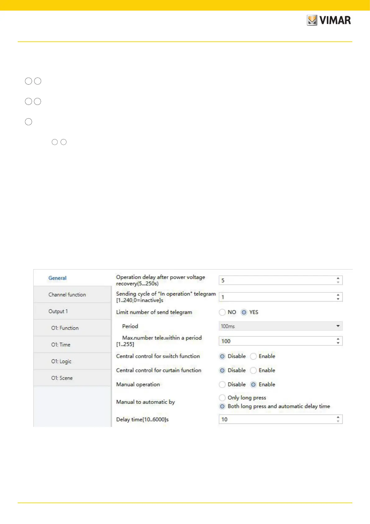
4.1 Parameter window “General”
The parameter window “General” setting interface is shown in Figure 4.1. This interface is used to set some common parameters and apply to each function block.
Fig. 4.1 Parameter window “General”
Dimension and Connection Diagram - Parameter setting description in the ETS
Bekijk gratis de handleiding van Vimar 01532, stel vragen en lees de antwoorden op veelvoorkomende problemen, of gebruik onze assistent om sneller informatie in de handleiding te vinden of uitleg te krijgen over specifieke functies.
Productinformatie
| Merk | Vimar |
| Model | 01532 |
| Categorie | Niet gecategoriseerd |
| Taal | Nederlands |
| Grootte | 15582 MB |


