Vestil TRI-AF handleiding
Handleiding
Je bekijkt pagina 9 van 10
0813 Rev. 12/6/2017 TRI, MANUAL
Copyright 2017 Vestil Manufacturing Co. Page 9 of 10
Using the tripod
Attach a chain hoist or other lifting device to the eyelet.
The capacity of the hoist should equal the capacity of the tripod. Subtract the weight of the
hoist from the capacity of the tripod. DO NOT exceed the capacity of the tripod or the hoist, whichever is
smaller. The capacity of each tripod model is listed in the table on p. 7 and displayed on label 287 (see
“Label placement diagram” below).
Adjust the length of each leg as needed to allow the hoist chain/cable, etc. to hang vertically. The legs of
models TRI-SA and TRI-AA can be adjusted in 6 inch increments. To adjust the length of a leg:
1. Align the appropriate pin hole in the inner leg tube with the pin holes in the outer leg tube.
2. Insert a ½ in. x 4½ in. clevis pin through the pin holes in both tubes; and
3. Secure the clevis pin with a
1
/
8
in. x 2
5
/
8
in. #11 hitch pin.
Inspections & Maintenance
Before putting the tripod into service, inspect it closely. Make a written record that describes the
appearance of each component as well as the finish (paint/powder coat). Include observations about
connections between components, e.g. legs, top casting, and feet. This written record establishes
“normal condition”. Inspect the unit before each use. Compare inspection results to the written record to
determine if the unit is in normal condition. Complete all repairs and replacements necessary to restore
the unit to normal condition BEFORE using it again.
Before each use, inspect the listed components. Do not use the tripod unless all components are in
normal condition:
1. Top casting: the top casting should be square and rigid and should lack cracks, warps, etc.
2. Leg tubes: confirm that the attachments to the top casting and to the foot castings are sound. Also
examine the ends of all leg tubes for flares, cracks, bends, and warps.
3. Clevis pins, hitch pins and pin holes: inspect all of the clevis pins (part numbers 66125 & 66123 in
the exploded parts diagrams). Check pin holes for elongations, cracks, and deformation. Confirm
that pins are straight and without cracks or warps.
4. Eyebolt and fasteners (hardware): tighten loose fasteners and replace any fastener that is
damaged;
5. Hinge link assembly (powered units): confirm that the link assembly is not warped or cracked
6. Crossbar support (manual models): examine the crossbar and confirm that it is structurally sound.
For example, it should not be warped, cracked, bent, or excessively rusted or corroded.
7. Product labels: all labels should be readable and located as shown below. Replace all labels that
are unreadable or missing.
8. Overall condition of the tilter: the structure should be clean, square and rigid, and free of rust and
corrosion. Remove dirt and debris.
9. Chains: check all chains and
5
/
16
in. quick links for elongations, cracks, and deformation.
10. Welds: confirm that all welds are intact.
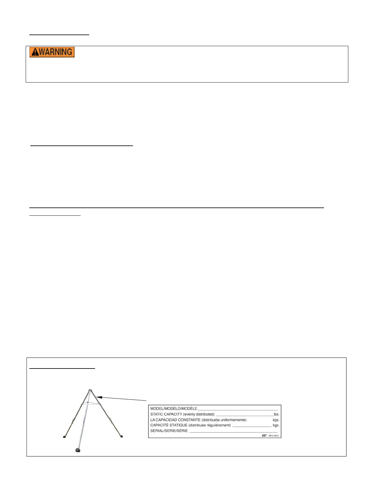
Labeling diagram
Each tripod should be labeled as shown on this page. Replace any label that is damaged or unreadable.
DO NOT use the tripod unless all labels are in place.
Label 287
Bekijk gratis de handleiding van Vestil TRI-AF, stel vragen en lees de antwoorden op veelvoorkomende problemen, of gebruik onze assistent om sneller informatie in de handleiding te vinden of uitleg te krijgen over specifieke functies.
Productinformatie
| Merk | Vestil |
| Model | TRI-AF |
| Categorie | Niet gecategoriseerd |
| Taal | Nederlands |
| Grootte | 1864 MB |


