Vestil HBD-6-60 handleiding
Handleiding
Je bekijkt pagina 5 van 21
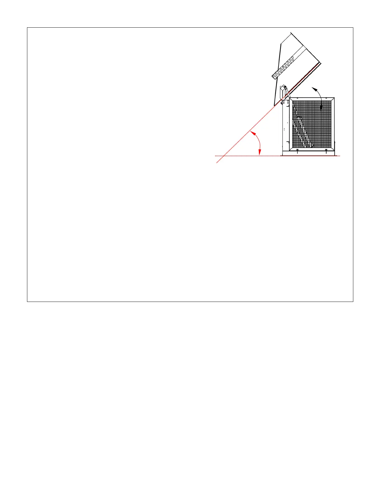
Table of Contents 3/30/2020 HBD MANUAL
Table of Contents Copyright 2019 Vestil Manufacturing Co. Page 5 of 21
INSPECTIONS
Compare the results of each inspection to the Record of Satisfactory Condition.
Do not use the machine unless it is in satisfactory condition.
Before each use, inspect the listed components:
1. Wires: look for frays;
2. Hydraulic system: check lines for chafes, pinches or leaks, and
the reservoir for punctures or leaks;
3. Container-restraining tube (and holes in the chute that receive
each end of the tube): Damage, deformation, looseness of fit.
4. Frame: check the cylinder brackets, vertical and horizontal
frame members, horizontal cross-member, and angle cross
member, hinge blocks, and pivot shaft and spacer assemblies
for cracking, deformation and corrosion;
5. Limit switches: Cycle the chute. The chute should not rotate
beyond approximately 45 degrees or below 0 degrees. See
FIG. 1.
Listen for unusual sounds that might indicate binding or grinding
during operation and watch for erratic movement(s). Contact
maintenance personnel if you observe any unusual sound or
movement and do not use the dumper until approved for service.
At least once per month, inspect the dumper as follows:
1. Oil level: fully raise the chute (to the 45°) “dumping position,” and then observe the level of oil in the reservoir. The
surface of the oil should be 3 to 3½ inches below the fill hole.;
2. Pivot points: check the dumper for excessive wear at the pivot points between hydraulic cylinders and cylinder
brackets, and between pivot shafts and hinge blocks;
3. Floor connection points: anchor bolts should prevent the frame from lifting off of the ground during chute
operation. Concrete around each anchor bolt should be intact—no cracking or flaking;
4. Fasteners: check each fastener connection. Tighten any loose connection;
5. Hoses and wires: check each wire and hose for damage (fraying, binding, etc.);
6. Labels: labels should be easily readable and undamaged, affixed to the dumper in the locations as shown in the
Labeling Diagram on p. 21.
7. Container-restraining tube (and the openings in the chute that receive each end of the tube): inspect the tube for
damage deformation, looseness of fit.
At least once per year, change the hydraulic oil if it becomes gritty or looks milky (water present in the oil). With
the chute in the fully lowered position, drain the oil and replace it with either Dexron transmission fluid or anti-wear
hydraulic oil, viscosity grade 150 SUS at 100°F (ISO 32 cSt at 40°C).
POWER UNIT OPERATION
NOTE 1: Box dumpers made after 12/01/18 receive a redesigned modular power unit, designated MPU GEN2.
Diagrams and operation instructions for GEN2 power units are provided in a separate instruction manual.
NOTE 2: Standard HBD units, i.e. not equipped with high cycle power unit, are not designed for high cycle use. High
cycle use is defined as 12-15 motor starts per hour for 3 or more consecutive hours. If your application requires high
cycle use, you must upgrade the standard power unit with a high cycle power unit.
The box dumper utilizes an electric motor directly coupled to a gear pump to pressurize the hydraulic fluid. Fluid
pressure moves the cylinders up or down, and this movement performs the work required to raise and lower the
chute. A hydraulic manifold bolted directly onto the gear pump houses the hydraulic control components; each
component is rated for 3,000psi working pressure.
Important components of the power unit include:
• Electric motor: when ordered, the owner of this box dumper selected either a single-phase or three-phase AC
motor. Regardless of phase capabilities, every motor is dual-voltage capable.
• Gear pump: shaft coupled directly to the shaft of the electric motor. Several displacements are available are
correspond to the horsepower of the motor selected.
• Check valve (HBD-2-## and HBD-4-## models): prevents backflow of fluid through the pump and thereby allows
the chute maintain a given position indefinitely.
• Pressure relief valve: opens a path for fluid to flow back to the reservoir if fluid pressure exceeds 3,000psi.
• Lowering solenoid valve: electrically-operated cartridge valve with an integral screen to keep contaminants from
entering the valve.
• Counterbalance valves (6,000lb. rated load models only): allow smooth motion in double-acting hydraulic circuits.
45°
Dumping
position:
Chute
raised
45°
Bekijk gratis de handleiding van Vestil HBD-6-60, stel vragen en lees de antwoorden op veelvoorkomende problemen, of gebruik onze assistent om sneller informatie in de handleiding te vinden of uitleg te krijgen over specifieke functies.
Productinformatie
| Merk | Vestil |
| Model | HBD-6-60 |
| Categorie | Niet gecategoriseerd |
| Taal | Nederlands |
| Grootte | 5500 MB |


