USL LSS-200 handleiding
Handleiding
Je bekijkt pagina 25 van 34
21
TD-001538-01-A1
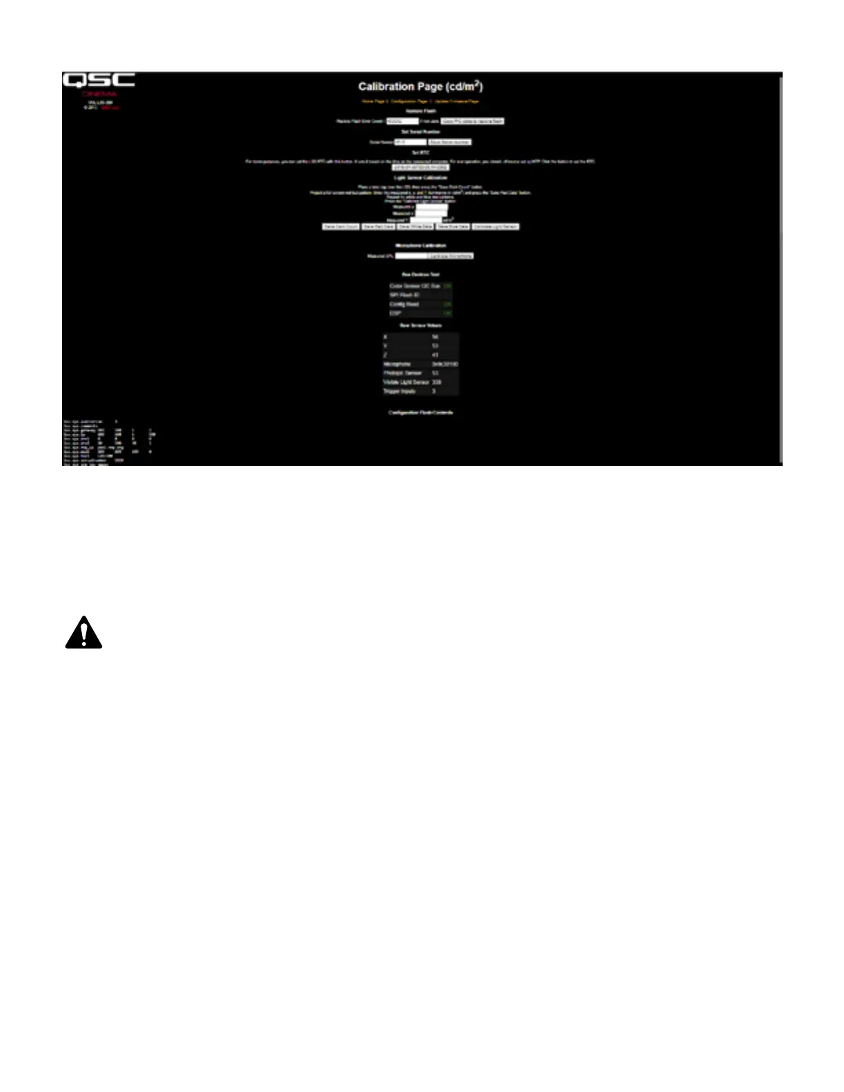
— Figure 20 — LSS-200 Calibration Screen
Besides calibration, these screens includes factory configuration features and debug information.
The Copy PIC code to restore flash copies the currently loaded firmware to external flash as a backup. The number to the left of this button is a
count of how many bytes disagree. We recommend not clicking this button in the field. Keeping the factory firmware as a backup allows you to go
back to it should something go wrong.
RNOT: Copy PIC code to restore flash and Set Serial Number both copy the default script to configuration memory, replacing any
custom script. Use of Copy PIC and Set Serial Number in the field is discouraged.
The Set Serial Number button is not normally used in the field. The MAC address of the LSS-200 is based on the serial number.
Use the procedure below to calibrate the light portion of the LSS-200:
1. Present the LSS-200 with total darkness. This can be accomplished by putting a lens cap over the lens or by dowsing the projector and
removing power from any IR panels in the auditorium. Once the LSS-200 is presented with total darkness, click the “Save Dark Count” button.
This sets a dark reference for the XYZ sensor.
2. Project a full-screen red test pattern on the screen. Measure the color (x,y) and luminance with the spectrometer-based reference meter. While
the test pattern is still on the screen, key these values into the “measured x,” “measured y”, and “measured Y” (luminance) fields, then click
“Save Red Data.”
3. Project a full-screen white test pattern on the screen. Measure the color (x,y) and luminance with the spectrometer-based reference meter.
While the test pattern is still on the screen, key these values into the “measured x,” “measured y”, and “measured Y” (luminance) fields, then
click “Save White Data.”
4. Project a full-screen blue test pattern on the screen. Measure the color (x,y) and luminance with the spectrometer-based reference meter.
While the test pattern is still on the screen, key these values into the “measured x,” “measured y”, and “measured Y” (luminance) fields, then
click “Save Blue Data.”
5. Click the “Calibrate Light Sensor” button.
To calibrate the SPL meter, place a sound level calibrator, such as the Reed SC-05 over the LSS-200 microphone. Set the sound calibrator to 94
dB. Key 94 into the Measured SPL field, then click the Calibrate Microphone button.
The remainder of the screen includes information to aid in the production test of the LSS-200. It can be ignored while doing field calibration of the LSS-200.
Bekijk gratis de handleiding van USL LSS-200, stel vragen en lees de antwoorden op veelvoorkomende problemen, of gebruik onze assistent om sneller informatie in de handleiding te vinden of uitleg te krijgen over specifieke functies.
Productinformatie
| Merk | USL |
| Model | LSS-200 |
| Categorie | Niet gecategoriseerd |
| Taal | Nederlands |
| Grootte | 6136 MB |


