USL LSS-200 handleiding
Handleiding
Je bekijkt pagina 14 van 34
10
TD-001538-01-A1
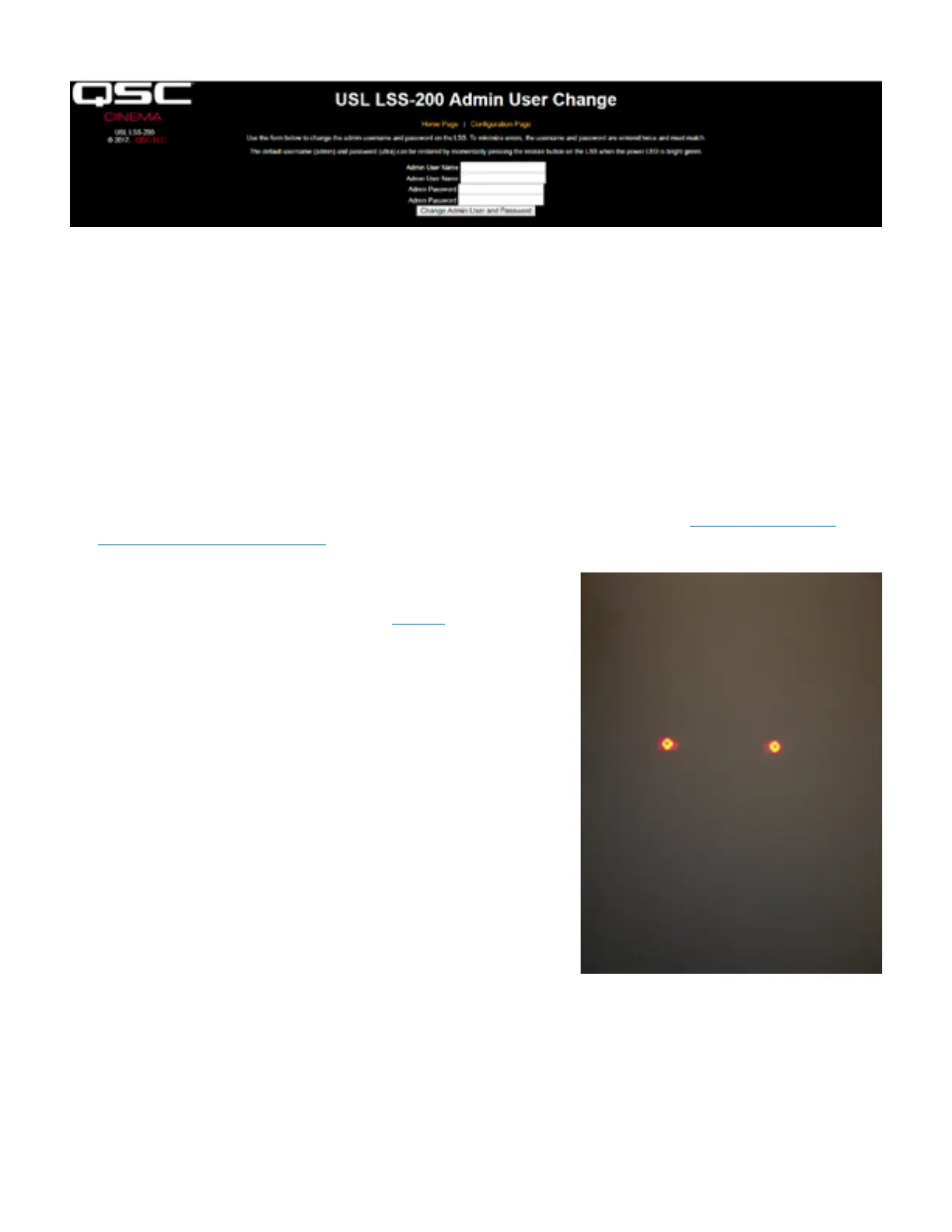
— Figure 10 — Admin User Change page
Installation
1. Use the supplied OmniMount 10.0 wall mount to attach the LSS-200 to the auditorium back wall.
a. Aim the lens and microphone towards the screen.
b. Thread the supplied nut onto the OmniMount threaded rod with the flat side of the nut towards the threaded end and away from the ball.
c. Thread the OmniMount threaded rod into the threaded hole on the LSS-200 turning the LSS-200 four turns, adjusting a fraction of a turn as
required to point the LSS-200 towards the screen.
d. Tighten the nut on the threaded rod against the LSS-200 case to firmly mount the LSS-200 to the threaded rod.
2. If necessary, drill a hole between the booth and auditorium for the wiring. Since the LSS-200 uses Power Over Ethernet, only an Ethernet
cable needs to be run. Connect the Ethernet cable between the LSS-200 and a user-supplied PoE Ethernet switch or PoE injector (IEEE
802.3af class 1 or “passive 48V”) to power the unit. If a PoE injector is used, connect another cable from the injector to the auditorium
Ethernet switch. If desired, the LSS-200 may instead be powered using a USB cable and power supply (see Appendix B – USB Power
Interface and Contact Closure Script Start).
3. Turn the LSS-200 LED switch to on and adjust the focus control until the red spots
on the screen appear to be in focus. As the LSS-200 is adjusted out of focus, the
hole in the middle of the spots fills in. When the LSS-200 is in focus, the hole in the
center will be open and the edges sharp as shown in Figure 11. Once focus is set,
lock the lens position by tightening the thumb screw on the lens tube.
4. Project the test pattern on the screen. Suggested test content is the QSC LST-200
DCP. It is available from QSC on a USB flash drive or can be downloaded from http://
ftp.uslinc.com/?dir=ftp/Products/LSS-200/Software/TestContent . Position the LED
spots to be in the center of the test pattern area. Since the projector lamp is much
more powerful than the LEDs in the LSS-200, it may be difficult to see the LED spots
when the test pattern is on. A simple method of seeing where the LED spots are
within the test pattern is to wave a hand through the projector beam, casting a shadow
on the screen. As the shadow moves across the screen, the LED spots and their
location within the test pattern will become visible. The LSS-200 sensor is positioned
midway between the LEDs. Rotate the LSS-200 to align the spots horizontally within
the test pattern. Place the center of the area between the spots in the center of the
test pattern area. Lock the Omnimount position and turn off the LEDs.
5. The luminance and color (x, y) should agree with an accurate color meter.
Spectrometer-based color meters are the most accurate. Note that luminance varies
with measurement position due to the incident angle of the projector light with the
screen and screen gain. Note that the LSS-200 is factory calibrated with a xenon-
based projector. If another illumination source is used in the projector (such as
laser or laser-phosphor), the LSS-200 will have to be calibrated in place using the
procedure on page 20.
6. Turn on a pink noise source on one of the auditorium speakers (or play the test DCP
which contains pink noise on each speaker in sequence). The SPL indicated by the LSS-200 should be close to that measured with an SPL
meter. Again, due to system tolerances and variations in sound level throughout the auditorium, the numbers will not match precisely.
— Figure 11 — LSS-100 LED Focus and Aim
Bekijk gratis de handleiding van USL LSS-200, stel vragen en lees de antwoorden op veelvoorkomende problemen, of gebruik onze assistent om sneller informatie in de handleiding te vinden of uitleg te krijgen over specifieke functies.
Productinformatie
| Merk | USL |
| Model | LSS-200 |
| Categorie | Niet gecategoriseerd |
| Taal | Nederlands |
| Grootte | 6136 MB |


