Supermicro X14SBT-GAP handleiding
Handleiding
Je bekijkt pagina 52 van 142
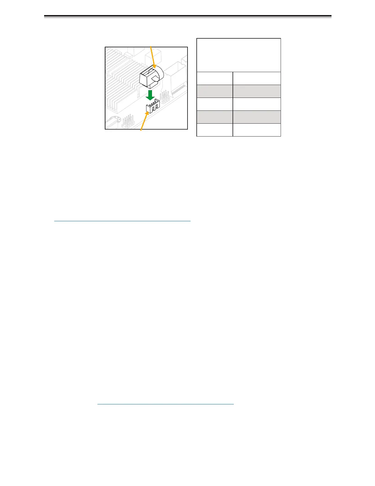
Intel VROC Key
Pin Definitions:
Four Total
Pin# Definition
1 GND
2 +3.3 V Standby
3 GND
4 CPU RAID Key
Note: Images displayed are for illustrative purposes only. The components installed in your
system may or may not look exactly the same as the graphics shown in the manual.
Note: For detailed instructions on how to configure VROC RAID settings, refer to the VROC
RAID Configuration User's Guide posted on the web page under the following link:
https://www.supermicro.com/support/manuals.
MCIO PCIe 5.0 p52-x8 Connectors
Mini Cool Edge IO (MCIO) PCIe 5.0 x8 connectors are located at JPCIE1A1, JPCIE1B1,
JPCIE2A1, JPCIE2B1, JPCIE3A1, JPCIE3B1, JPCIE4A1, and JPCIE4B1 on the X14SBT-GAP
motherboard.
For a detailed diagram of the X14SBT- GAP motherboard, see the layout under "Quick
Reference" on page 12.
NC-SI Connection
The Network Controller Sideband Interface (NC-SI) connection is located on the X14SBT-GAP
motherboard. This connection is used to connect a Network Interface Card (NIC) to the
motherboard to allow the onboard Baseboard Management Controller (BMC) to communicate
with a network.
Note: For detailed instructions on how to configure Network Interface Card (NIC) settings,
refer to the Network Interface Card Configuration User's Guide posted on the web page
under the link: https://www.supermicro.com/support/manuals.
For a detailed diagram of the X14SBT- GAP motherboard, see the layout under "Quick
Reference" on page 12.
52
X14SBT-GAP: Component Installation
Bekijk gratis de handleiding van Supermicro X14SBT-GAP, stel vragen en lees de antwoorden op veelvoorkomende problemen, of gebruik onze assistent om sneller informatie in de handleiding te vinden of uitleg te krijgen over specifieke functies.
Productinformatie
| Merk | Supermicro |
| Model | X14SBT-GAP |
| Categorie | Niet gecategoriseerd |
| Taal | Nederlands |
| Grootte | 15560 MB |


