Supermicro X14SAE handleiding
Handleiding
Je bekijkt pagina 9 van 11
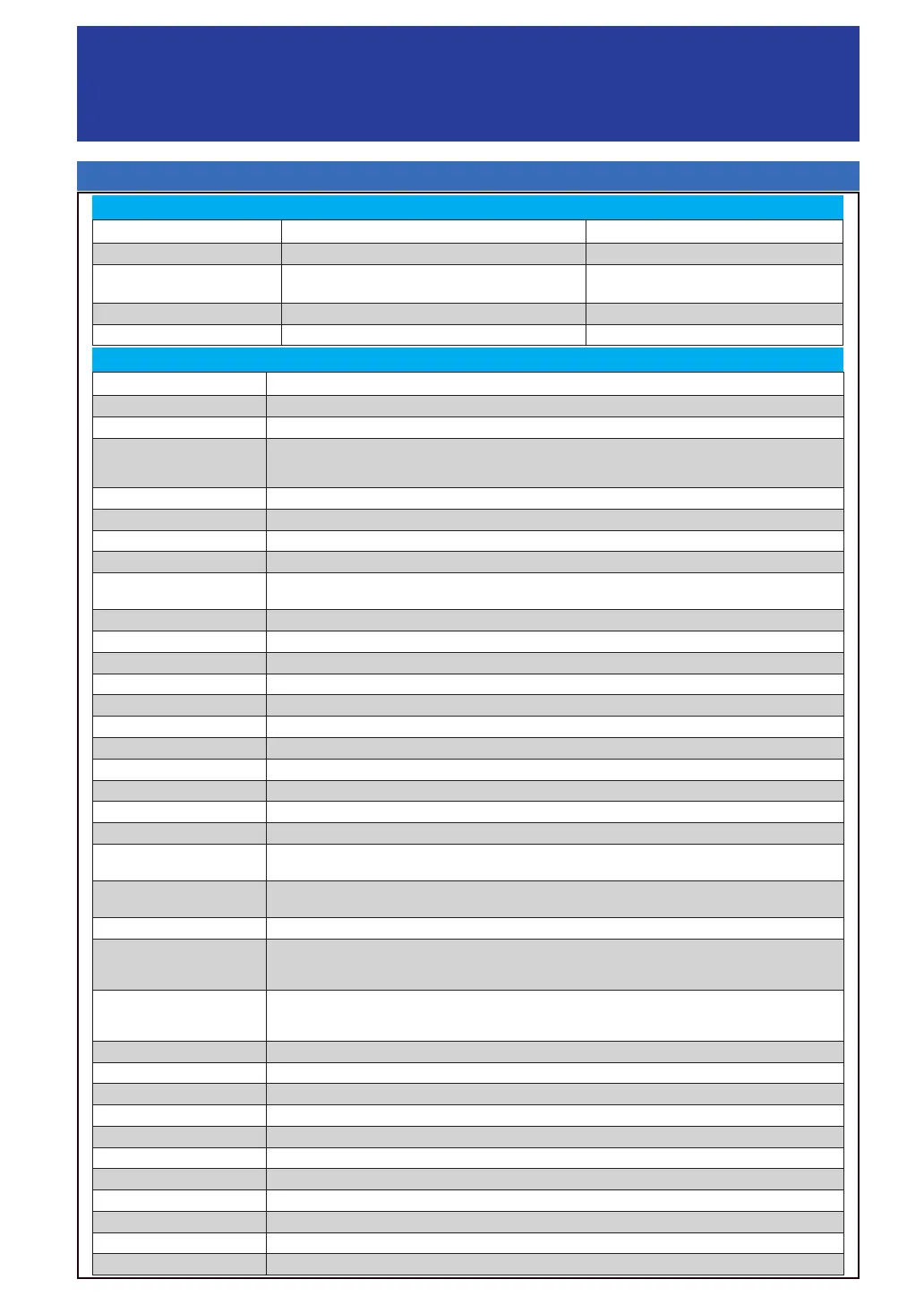
Package contents
• One Supermicro Motherboard
• Eight SATA Cables
• One I/O Shield
• One Quick Reference Guide
Connector Description
12V_PUMP1 4-pin +12 V Power Connector (for CPU liquid cooling pump)
AUDIO Rear High Denition Audio Ports
AUDIO FP
Front Audio Header
* The default setting is for a headphone/microphone combo jack. If not using a chassis with the headphone/microphone
combo jack, congure Frontside Audio Mode in the BIOS Setup utility. Refer to User's Manual for detailed instructions.
BMC_LAN Dedicated BMC LAN Port (X14SAE-F only)
BT1 Onboard Battery
COM1 COM Header
DP_HDMI
DP: Rear DisplayPort 2.1. HDMI: High Denition Multimedia Interface 2.1
FAN1, FAN1A, FAN2B, FANA
FAN2, FAN3, FAN3C
FAN1, FAN1A, FAN2B, FANA: System Fan Headers
FAN2, FAN3, FAN3C: CPU Fan Headers
I-SATA0–I-SATA7 SATA 3.0 Ports (from Intel
®
PCH, 6 Gb/sec, with support of RAID 0, 1, 5, and 10)
JFP1 Front Control Panel Header
JL1 Chassis Intrusion Header
JLED1 3-pin Power LED Header
JPI2C1 Power Supply SMBus I2C Header (X14SAE-F only)
JPW1 24-pin ATX Main Power Connector (Required)
JPW2 8-pin +12 V CPU Power Connector (Required)
JSD1 SATA Disk-On-Module (DOM) Power Connector
JSTBY1 Standby Power Header (5 V)
JTPM1 Trusted Platform Module (TPM)/Port 80 Header (TPM 2.0 only)
LAN1, LAN2 LAN1: RJ45 1 GbE LAN Port. LAN2: RJ45 2.5 GbE LAN Port
M.2-C1
PCIe 5.0 p9-x4 M.2 M-key Slot (from CPU, with support of 2280 form factor)
* M.2-C1 and M.2-P1 can be mixed to support RAID 0 and 1.
M.2-P1
PCIe 4.0 p9-x4 M.2 M-key Slot (from PCH, with support of 2280 and 22110 form factors)
* M.2-P1 and M.2-C1 can be mixed to support RAID 0 and 1.
PCH_PE1 0-7 (x4/ x4) PCIe 4.0 p9-x8 SlimSAS 8i Side-facing Connector supporting two U.2 connections (from PCH)
SLOT3
PCIe 5.0 p9-x8 (IN x16) Slot (from CPU, with support of 1x8 or 2x4 bifurcation)
* SLOT3 will be enabled only when SLOT6 is populated.
* SLOT3 supports single-width and double-width graphics cards.
SLOT6
PCIe 5.0 x16 Slot (from CPU, with support of 1x8 or 1x16 bifurcation)
* SLOT6 will function at PCIe 1x8 when SLOT3 is populated or when SLOT3 is congured to 2x4 bifurcation mode.
* SLOT6 supports storage and graphics cards only.
SLOT7 PCIe 4.0 p9-x4 Slot (from CPU)
SP1 Internal Speaker/Buzzer
UID-SW Unit Identier (UID) Switch (X14SAE-F only)
USB0/1 Front Accessible USB 2.0 Header
USB2/3 Front Accessible USB 3.2 Gen 1x1 Header (5 Gb)
USB4 Front Accessible USB 3.2 Gen 1x1 Header (5 Gb, Vertical)
USB5–USB7 Rear USB 3.2 Gen 2x1 Ports (10 Gb, Type-A)
USB8 Rear USB 3.2 Gen 2x2 Port (20 Gb, Type-C)
USB9 Front Accessible USB 3.2 Gen 2x2 Header (20 Gb, Type-C)
USB10 Rear Thunderbolt
TM
4 (TBT 4) Port (40 Gb, Type-C)
VGA VGA Port supported by BMC (X14SAE-F only)
LED Indicators and Connectors
Connectors
LED Description Color/State
CATERR_LED Catastrophic Error LED Solid Orange: System CATERR
LEDBMC
X14SAE: Standby Power LED
X14SAE-F: BMC Heartbeat LED
X14SAE: Solid Green (Standby Power On)
X14SAE-F: Blinking Green (BMC Normal)
LEDPWR Onboard Power LED Solid Green: Power On
UID Unit Identier (UID) LED (X14SAE-F only) Solid Blue: Unit Identied
LED Indicators
Bekijk gratis de handleiding van Supermicro X14SAE, stel vragen en lees de antwoorden op veelvoorkomende problemen, of gebruik onze assistent om sneller informatie in de handleiding te vinden of uitleg te krijgen over specifieke functies.
Productinformatie
| Merk | Supermicro |
| Model | X14SAE |
| Categorie | Niet gecategoriseerd |
| Taal | Nederlands |
| Grootte | 1852 MB |


