Supermicro X14DBT-F handleiding
Handleiding
Je bekijkt pagina 14 van 137
Notes:
l
See "Component Installation" on page 27 for detailed information on jumpers,
connectors, and LED indicators.
l
"■" indicates the location of pin 1.
l
Components not documented are for internal testing-purposes only.
l
Use only the correct type of onboard CMOS battery as specified by the manufacturer.
Do not install the onboard battery upside down to avoid possible explosion.
Quick Reference
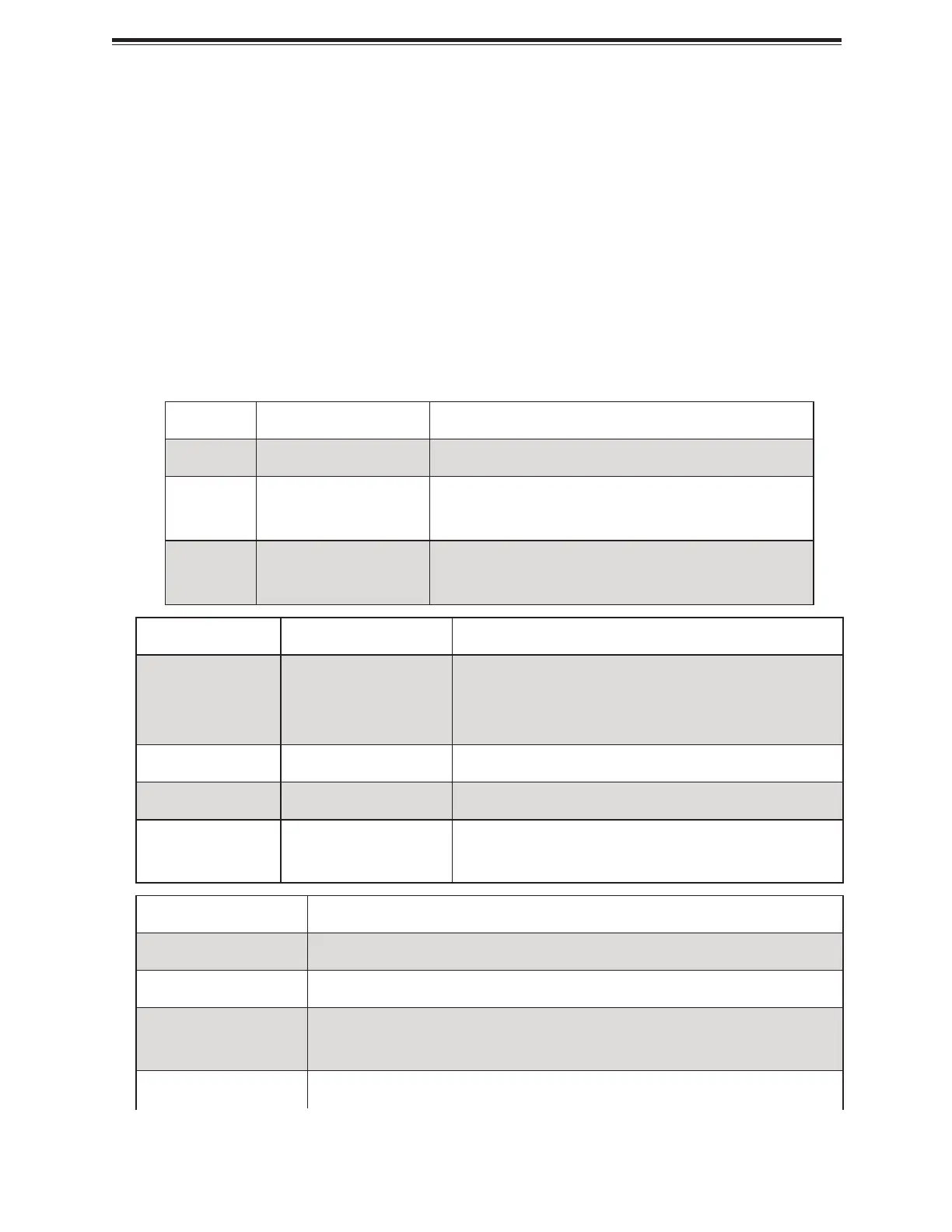
Jumper Description Jumper Settings
JBT1 CMOS Clear Open (normal)
JPFR2 Updates PFR
Off (Pin 1–1): Normal (Default),
Debug Key On (Pin 1–2): PFR Update, Production Key
JPFR3 Disables PFR Function
Off (Pin 1–1): Normal (Default),
On (Pin 1–2): Disable PFR
LED Description Status
LEDM1 (BMC
LED)
BMC Heartbeat LED
Blinking Green: BMC Normal (Active),
Solid Green: (During BMC Reset or during a Cold
Reboot)
LED3 (AUX LED) AUX LED LED On: +3.3 V AUX Power On
LED4 (LEDPWR) Onboard Power LED LED On: Onboard Power On
LED5
Unit Identifier
(UID) LED
Solid Blue: Unit Identification LED
Connector Description
BT1 Onboard Battery
FAN1–FAN4 Four 8-pin Cooling Fan Header
JAIOM1 (P1_PE1 0-
15)
Advanced Input/Output Module (AIOM) PCIe 5.0 x16 Connector for I/O
Support
JCOM1 Serial (COM) Header
14
X14DBT-FAP/-FLAP: Introduction
Bekijk gratis de handleiding van Supermicro X14DBT-F, stel vragen en lees de antwoorden op veelvoorkomende problemen, of gebruik onze assistent om sneller informatie in de handleiding te vinden of uitleg te krijgen over specifieke functies.
Productinformatie
| Merk | Supermicro |
| Model | X14DBT-F |
| Categorie | Niet gecategoriseerd |
| Taal | Nederlands |
| Grootte | 14774 MB |


