Supermicro MicroBlade MBI-311C-1C2 handleiding
Handleiding
Je bekijkt pagina 37 van 98
37
Chapter 3: Motherboard Connections
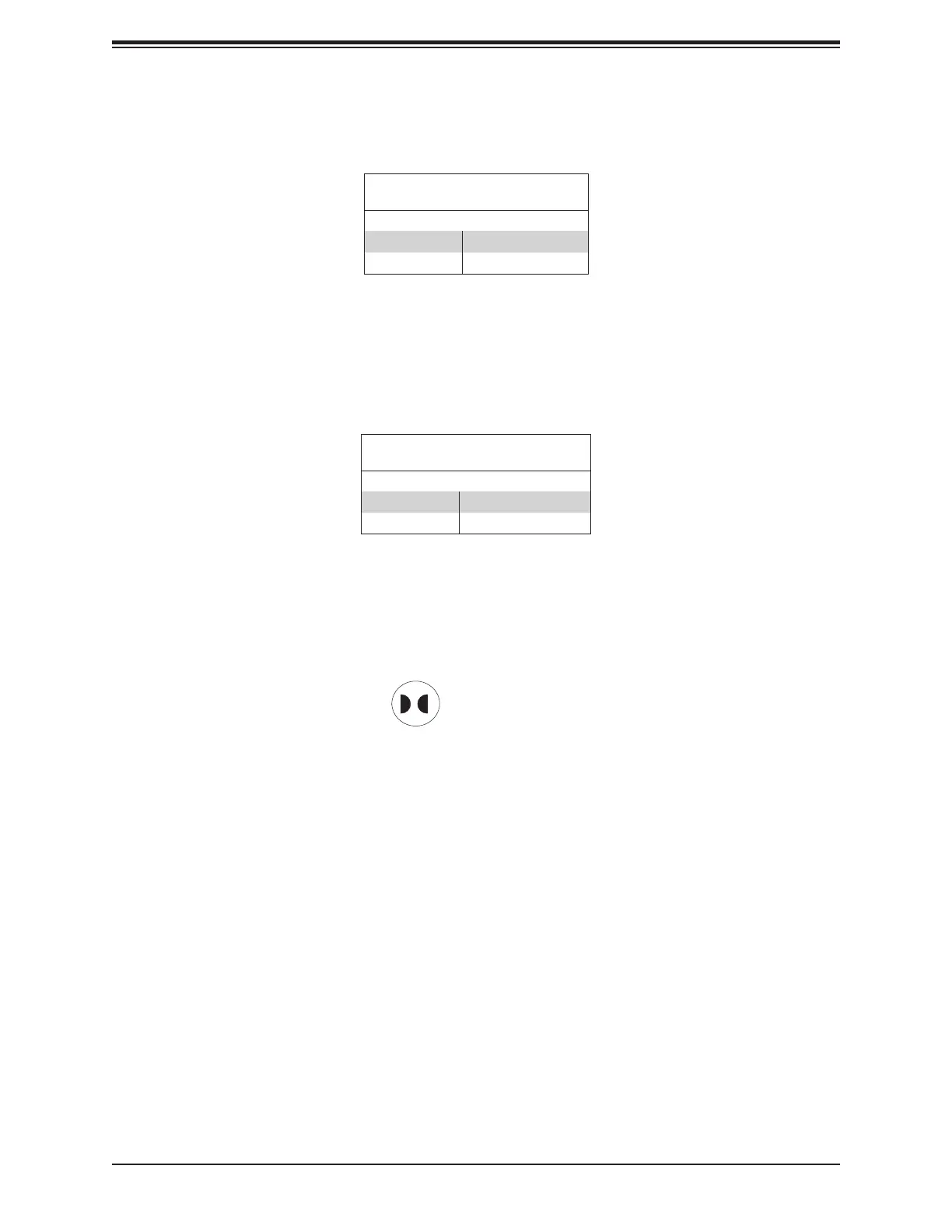
JBT1 contact pads
CMOS Clear Contacts
JBT1 is used to clear CMOS. Instead of pins, this jumper consists of contact pads. See the
CMOS Clear section for more information.
3.3 LED Indicators
BMC Heartbeat LED
LEDM1 is a BMC Heartbeat indicator. It blinks green when the BMC is working properly.
VGA Enable/Disable
Use jumper JPG1 to enable or disable the VGA port using the onboard graphics controller.
VGA Enable/Disable
Jumper Settings
Jumper Setting Denition
Pins 1-2 Enabled (Default)
Pins 2-3 Disabled
ME Manufacturing Mode
Close pins 2-3 of jumper JPME2 to bypass SPI ash security and force the system to operate
in the manufacturing mode, which will allow the user to ash the system rmware from a host
server for system setting modications.
Manufacturing Mode
Jumper Settings
Jumper Setting Denition
Pins 1-2 Normal (Default)
Pins 2-3 Manufacturing Mode
BMC Error LED
LED2 is the BMC error LED. When this LED is solid RED, the BMC detects a power or fan
failure. Refer to the table below for the LED status.
DDR5 PWRFAIL LED
LED3 is the DDR5 PWRFAIL LED. When this LED is solid red, a power failure is detected
in the DDR5 modules.
Bekijk gratis de handleiding van Supermicro MicroBlade MBI-311C-1C2, stel vragen en lees de antwoorden op veelvoorkomende problemen, of gebruik onze assistent om sneller informatie in de handleiding te vinden of uitleg te krijgen over specifieke functies.
Productinformatie
| Merk | Supermicro |
| Model | MicroBlade MBI-311C-1C2 |
| Categorie | Niet gecategoriseerd |
| Taal | Nederlands |
| Grootte | 19843 MB |


