Supermicro H14SST-GE handleiding
Handleiding
Je bekijkt pagina 13 van 103
Notes:
l
For detailed information on jumpers, connectors, and LED indicators, see "Component
Installation" on page 20.
l
"■" indicates the location of pin 1.
l
"MH" indicates the location of a mounting hole.
l
Components not documented are for internal testing purposes only.
l
Use only the correct type of onboard CMOS battery as specified by the manufacturer.
To avoid possible explosion, do not install the onboard battery upside down.
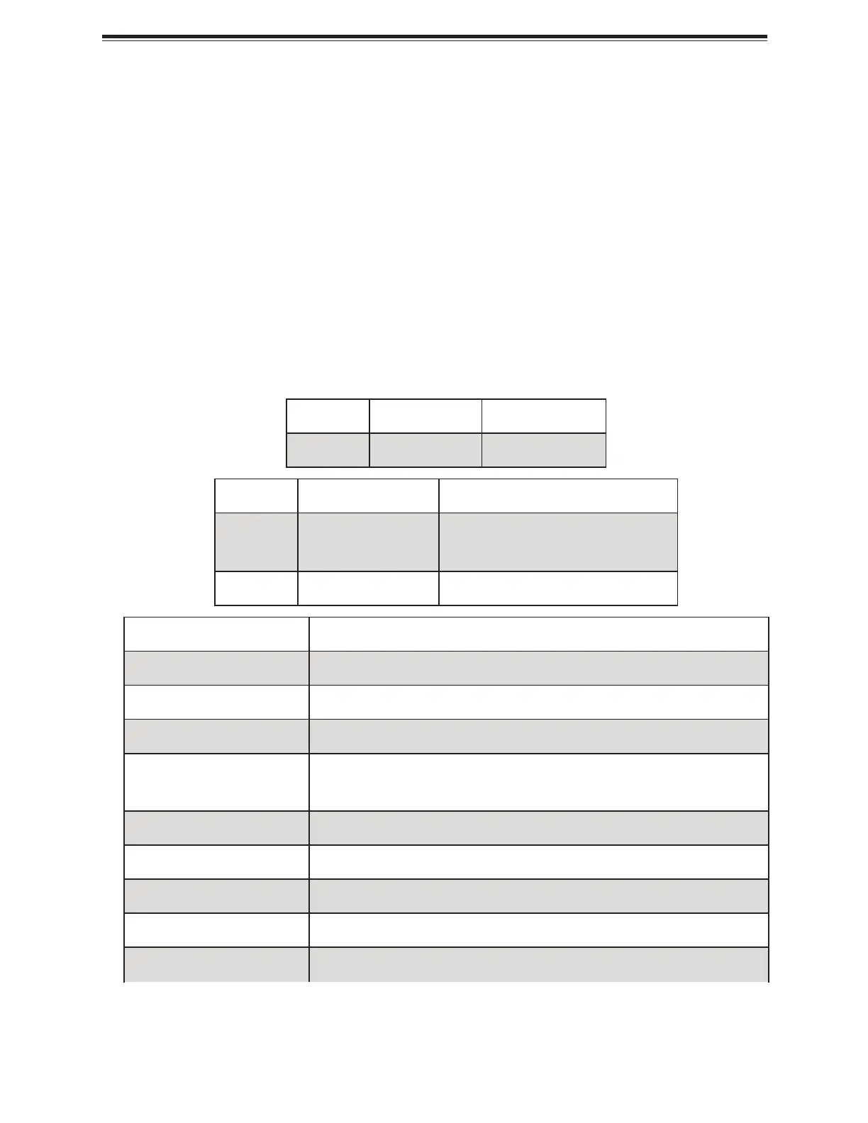
Quick Reference Table
Jumper Description Default Setting
JBT1 CMOS Clear Open (Normal)
LED Description Status
LEDBMC BMC Heartbeat LED
Green Blinking: BMC Normal
Green Blinking Fast: BMC Initializing
LEDPWR Onboard Power LED Solid Green: Power On
Connector Description
BT1 Onboard Battery
JAIOMSB1 Sideband Signal Header
JFIO1 Grand Twin Front IPMI and Onboard NIC Module Connector
JMCIO1–JMCIO4,
JMCIO6–JMCIO9
MCIO PCIe 5.0 x8 Connectors
JMCIO5 MCIO PCIe 5.0/SATA3 x8 Connector
JNCSI1 NC-SI Connector
JPDB1 Sideband Connector to GPU PDB
JPSU1 Power Supply Module Connector
JPW1, JPW5, JPW6 8-pin +12 V/+5 V Power Connector for SATA Backplane
13
H14SST-GE: Introduction
Bekijk gratis de handleiding van Supermicro H14SST-GE, stel vragen en lees de antwoorden op veelvoorkomende problemen, of gebruik onze assistent om sneller informatie in de handleiding te vinden of uitleg te krijgen over specifieke functies.
Productinformatie
| Merk | Supermicro |
| Model | H14SST-GE |
| Categorie | Niet gecategoriseerd |
| Taal | Nederlands |
| Grootte | 13111 MB |


