Supermicro A4SAN-E handleiding
Handleiding
Je bekijkt pagina 41 van 135
2.5 Connections, Jumpers, and LEDs
Refer to the following sections for information about connections, jumpers, and LEDs for the
A4SAN-H/-E/-L/-WOHS motherboard.
Main Power Connector
JPW1 is the 9 V–36 V DC power connector that provides power to the motherboard.
For a detailed diagram of the A4SAN-H/-E/-L/-WOHS motherboard, see the layout under
"Quick Reference" on page 11.
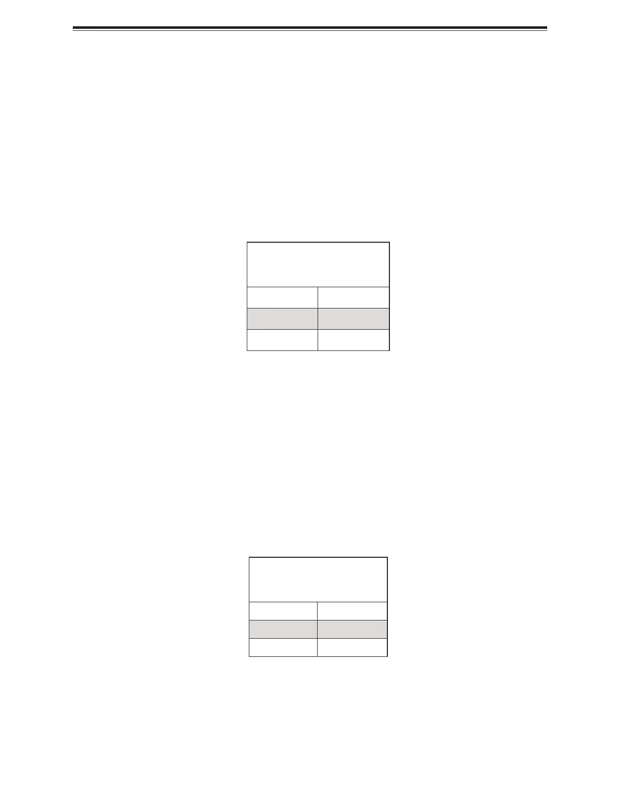
8-pin 9 V–36 V Power
Pin Definitions: Eight Total
Pin# Definition
1–4 +9 V–36 V
5–8 GND
Headers and Connections
For information about the headers of the A4SAN-H/-E/-L/-WOHS motherboard, refer to the
following content.
CMOS Battery
BT1 is a 2-pin header for an external battery. This connector is also used to clear the CMOS.
To clear the CMOS, remove the battery, short pins 1–2 for more than 10 seconds and then
install the battery.
For a detailed diagram of the A4SAN-H/-E/-L/-WOHS motherboard, see the layout under
"Quick Reference" on page 11.
CMOS Battery
Pin Definitions: Two Total
Pin# Description
1 P3V_BATTERY
2 GND
41
A4SAN-H/-E/-L/-WOHS: Component Installation
Bekijk gratis de handleiding van Supermicro A4SAN-E, stel vragen en lees de antwoorden op veelvoorkomende problemen, of gebruik onze assistent om sneller informatie in de handleiding te vinden of uitleg te krijgen over specifieke functies.
Productinformatie
| Merk | Supermicro |
| Model | A4SAN-E |
| Categorie | Niet gecategoriseerd |
| Taal | Nederlands |
| Grootte | 15888 MB |


