Stamos S-MIGMA 250.IGBT handleiding
Handleiding
Je bekijkt pagina 8 van 33
14 15
Rev. 23.05.2022 Rev. 23.05.2022
No. Function and description
1. ERROR INDICATOR = The indicator lights in the following two situations:
a) If the machine has malfunctioned and cannot be operated.
b) If the cutting device has exceeded the standard working time, the protection mode is initiated
and the machine will stop functioning. This means that the machine is now being cooled in order
to be able to restore the temperature control again after the device has overheated. Therefore,
the machine is stopped. During this process, the red warning light on the front panel lights up. In
this case it is not necessary to unplug the device. The ventilation system may be left on in order to
enhance the cooling of the machine. When the red light goes dark, this means that the temperature
is set to the normal level and the unit can be put back into operation.
2. Power on indicator
3 Wire feed rate adjustment knob
4. MIG voltage adjustment knob
5. TIG / MMA welding current adjustment knob
6. TIG/MIG – MMA switch
7. INCHING – upon pressing this button, the welder starts with the wire feed. The wire will be fed
until the button is released. It is used to feed the wire, e.g. upon the reel replacement.
8. TIG control button connector
9. TIG torch current-gas cable socket
10. „-“ Negative output
11. „+“ Positive output
12. Welding polarisation change socket.
Connected to the positive pole – MIG welding
Connected to the negative pole – FLUX welding
13. MIG connection socket
14. On/off switch
15. 230V~ CO2 heater socket
16. TIG welding gas connector
17. MIG welding gas connector
18. Power cable
19. Wire reel
20. Wire guide
21. Welding polarisation change cable (MIG/FLUX)
EN
1
2
3
4
5
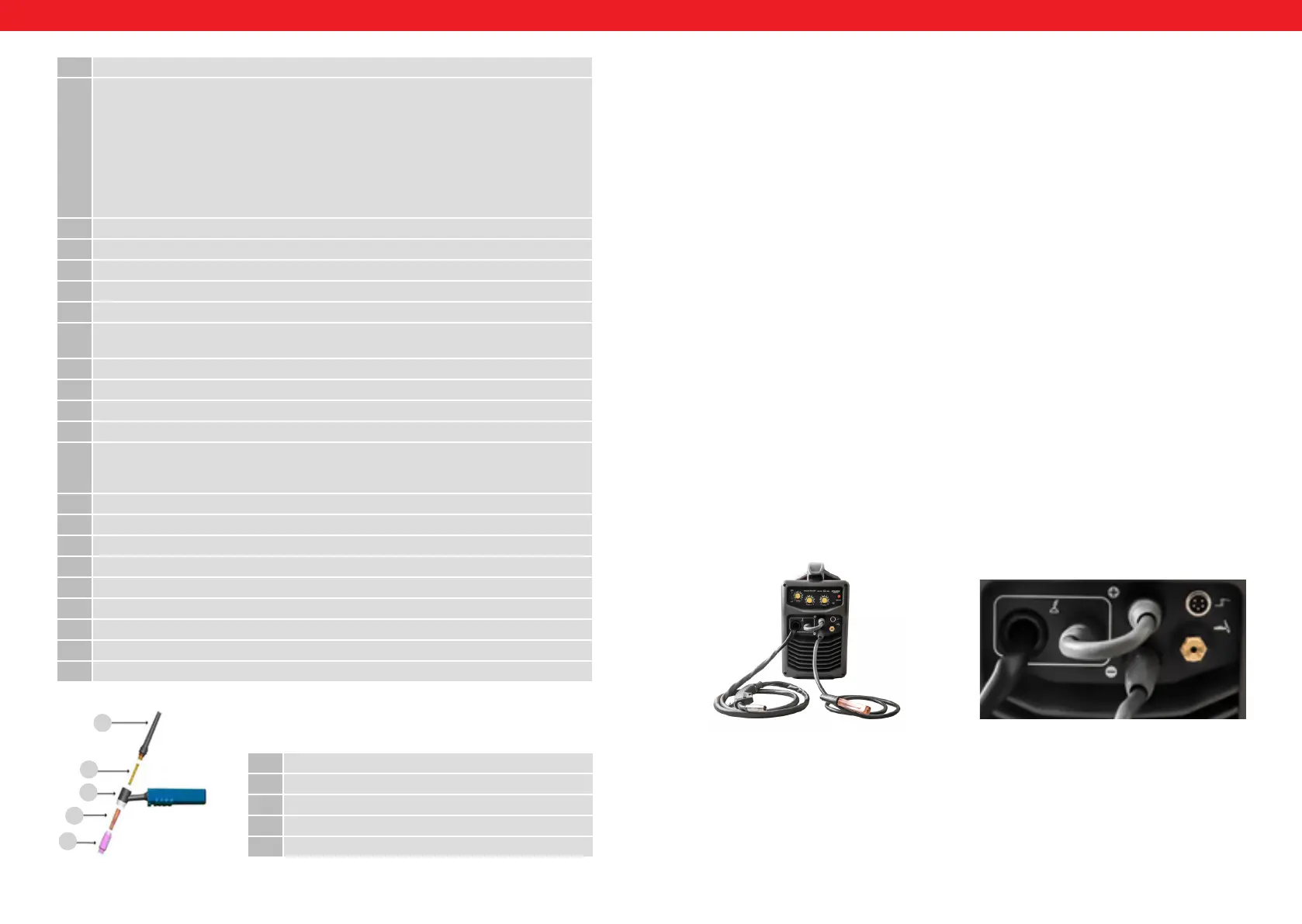
1. Back cap, long
2. Collet
3. Torch handle
4. Collet inside housing
5. Ceramic nozzle
TIG Griff:
5. CABLE CONNECTIONS
INSTRUCTIONS FOR CABLE CONNECTIONS:
Limit the number of cables connected to the unit at the same time. For example, during MIG welding,
no other welding cables (e.g. TIG) may be connected, because then the MIG welding will not work. This
procedure ensures proper functioning of the machine and the safety of the worker.
MMA WELDING MODE
1. Set the switch (6) to MMA welding mode.
2. Connect the mass cable to the socket marked with „+“ (11).
3. Then connect the cable with MMA electrode holder to socket marked with the „-“ sign (10).
WARNING! The polarization of the cables can be different! All polarisation information should be
shown on the packaging supplied by the electrode manufacturer.
4. Now you can connect the power cord and turn the power on, once the mass cable is connected to the
workpiece, you can start working.
TIG WELDING MODE
Before commencing with the TIG welding, connect the gas bottle to the socket in the rear of the machine,
marked with the number 16 on the diagram (TIG GAS).
1. Set the switch (6) to MIG/TIG welding mode.
2. Connect the mass cable to the socket marked with „+“ (11).
3. Connect the TIG torch current-gas cable to the connector (9) and the TIG control cable to the
connector (8).
4. Now you can connect the power cord and turn the power on, once the mass cable is connected to the
workpiece, you can start working.
MIG WELDING MODE
Before commencing with the MIG welding, connect the gas bottle to the socket in the rear of the machine,
marked with the number 17 (MIG GAS). Then connect the welding polarisation change cable to positive
socket (11) and to the socket marked with the number 12.
1. Set the switch (6) to MIG/TIG welding mode.
2. Connect the mass cable to the socket marked with „-“ (10).
3. Then insert the correct welding wire, connect the power cord and turn the power on, once the mass
cable is connected to the workpiece, you can start working.
FLUX WELDING MODE
Before commencing with the FLUX welding, connect welding polarisation change cable to negative socket
(10) and to the socket marked with the number 12.
1. Set the switch (6) to MIG/TIG welding mode.
2. Connect the mass cable to the socket marked with „+“ (11).
3. Then insert the correct welding wire, connect the power cord and turn the power on, once the mass
cable is connected to the workpiece, you can start working.
EN
Bekijk gratis de handleiding van Stamos S-MIGMA 250.IGBT, stel vragen en lees de antwoorden op veelvoorkomende problemen, of gebruik onze assistent om sneller informatie in de handleiding te vinden of uitleg te krijgen over specifieke functies.
Productinformatie
| Merk | Stamos |
| Model | S-MIGMA 250.IGBT |
| Categorie | Niet gecategoriseerd |
| Taal | Nederlands |
| Grootte | 8734 MB |